Welcome to our site! EDAboard.com is an international Electronics Discussion Forum focused on EDA software, circuits, schematics, books, theory, papers, asic, pld, 8051, DSP, Network, RF, Analog Design, PCB, Service Manuals... and a whole lot more! To participate you need to register. Registration is free. Click here to register now.
yes ,in sepic you only need to drive mosfet in low side ....so i am not using bootstrap o/p which is used when driving high side...right?is there any other mosfet that i can use????
What type or which value of series capacitor to use in this circuit...?can I use electrolytic or non polarized ???
Guys , I saw the output of the IR2110 and gives a nice 0-10v peak voltage when it is left open.....
When I connect it to the gate of mosfet, the peak voltage drops from 10v to around 7v ....I testing the output with 20w bulb rated at 12v...output current is limited by 1A and voltage is 11.7v .
I turned the mosfet fully on and let it to be ON with the bulb as load in the drain side ....the mosfet did not heat up ...It was same when mosfet was fully turned off..
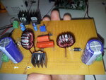
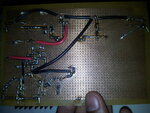
Guys ,I built a new circuit of sepic,with inductor values at 160-170uh...with huge capacitors at input and output...
Mosfet stays cool right now ...I tested the circuit with a 12v cpu fan....
The solar panel input was 18.5v and 0.11A ...[open circuit and short circuit]
When I connected to sepic, input dropped to 12.5v output was 6.1v...at 15% dutycycle I think...
today I am gonna add even bigger capacitors at the input side....
New problem...output voltage keeps rising without any load...when I put a 20w bulb,output volyage does not rise beyond 1v..and the inductor voltage is at 156v ...what might be the problem....should I use bigger inductor ?..can anyone guide me for proper sepic design...I have gone through many designs...but they all get different values for my design..also what ripple current should I choose???
At diode +ve and ground......
Now I am trying with 2.35mH inductor .....I am using 12v battery at input and cpu fan on output...the mosfet is not getting heated up ...but efficiency is poor..After 50% duty cycle ,output goes above 12v....but now at the same node,there is around 1200v...
Till 44% duty cycle ,there is no voltage at that node,but after that duty cycle ,236v is seen ...If i keep increasing the duty cycle , that node goes beyond 1000v.....
What to do?
Is my design correct?
This site uses cookies to help personalise content, tailor your experience and to keep you logged in if you register.
By continuing to use this site, you are consenting to our use of cookies.