Vermes
Advanced Member level 4
This is a description of simple and cheap construction of a stereo tube amplifier. This device was based on 6P14P – stronger counterparts of well known EL84 and additional tube with two triodes – ECC85.
In order to meet the assumption that the construction should be as cheap as possible, television transformers TG5-53 were used as speakers transformers. Those components have very well parameters among similar components easily available for an amateur.
The amplifier should take approximately 40W, so you need to select the transformer properly. It would be good if the transformer is also equipped with a shield between the primary and secondary windings, which is connected with the ground, what would eliminate interferences.
Schematic:
As you can see, it is a typical configuration of pentodes operating in A class, with components values selected accordingly to producer's recommendations. Switch marked as STDBY turns on amode voltage of tubes with a delay. This point is slightly modified – the switch is additionally equipped with resistor R16, which reduces the current surge of cold radiators of the tubes when the supply is on. There is also resistor R15 of small value applied in the glow circuit. That resistor corrects the glow voltage, because transformers used were designed to operate with voltage of 220V, not 230V.
The amplifier has a negative feedback loop, which reduces its sensitivity to approximately 0,5V rms, but improves stability of its operation. It is provided by separate winding for feedback in transformer TG5-53.
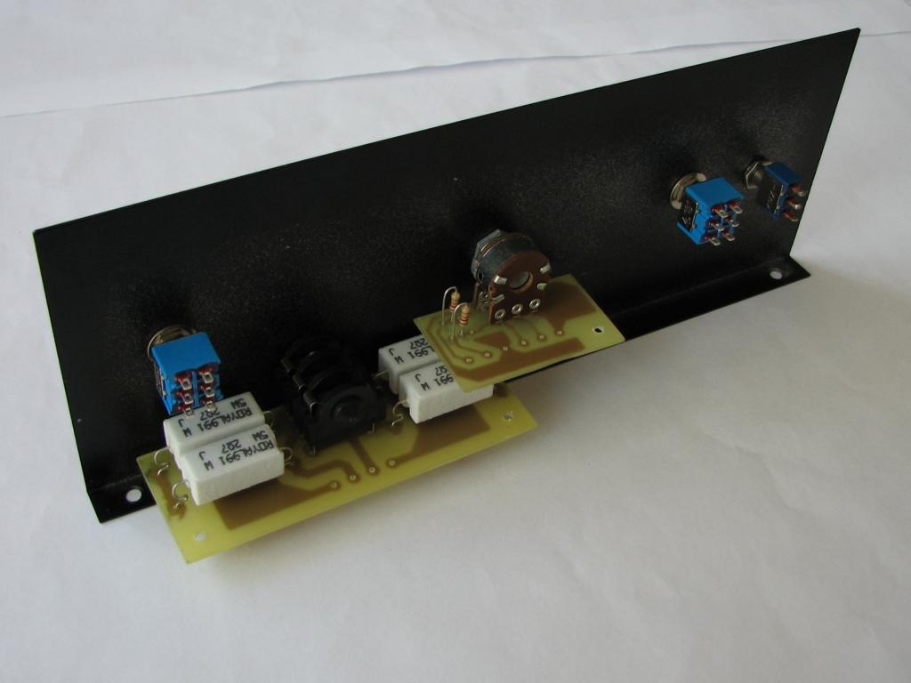
A socket for connection of headphones was additionally applied. Although almost all power is dispersed in resistors R10 operating as an artficial load during switching to headphones, you can connect headphones of any impedance. There is no possibility of damage, if the headphones disconnect for some reason, when the amplifier is on, and there is no problem with incorrect impedance. There are also additional resistors R11, which act as a protection, when you disconnect the speakers by a mistake, when the amplifier is on.
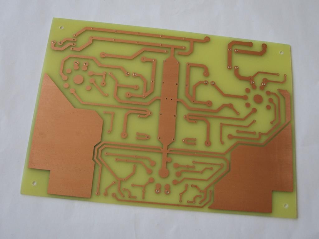
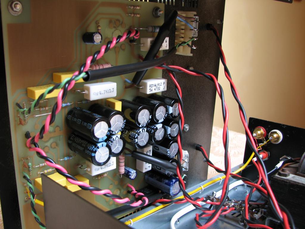
PCB:
The amplifier was performed on a PCB. There is a main board of the amplifier and two saller ones. On one of them there is headphones socket, and on the other – potentiometer for volume adjustment and additional potentiometers for additional damping is you want to reduce the sensitivity of the amplifier. Components on each of the PCBs were circled by dashed lines in the schematic. In addition, indicative values of voltages at different points of the circuit were marked on the schematic.
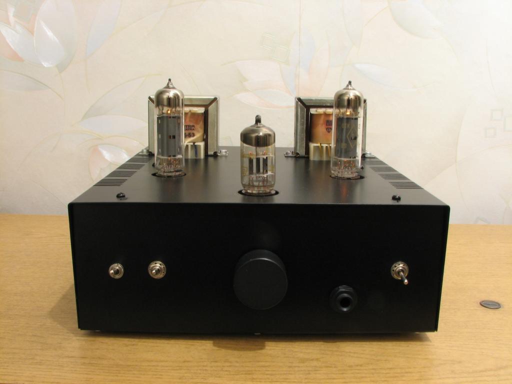
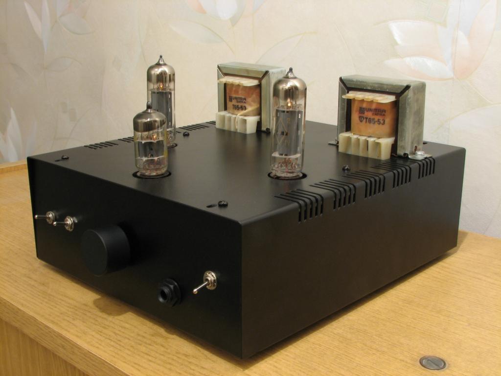
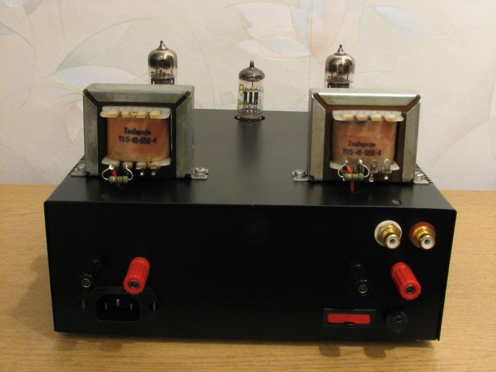
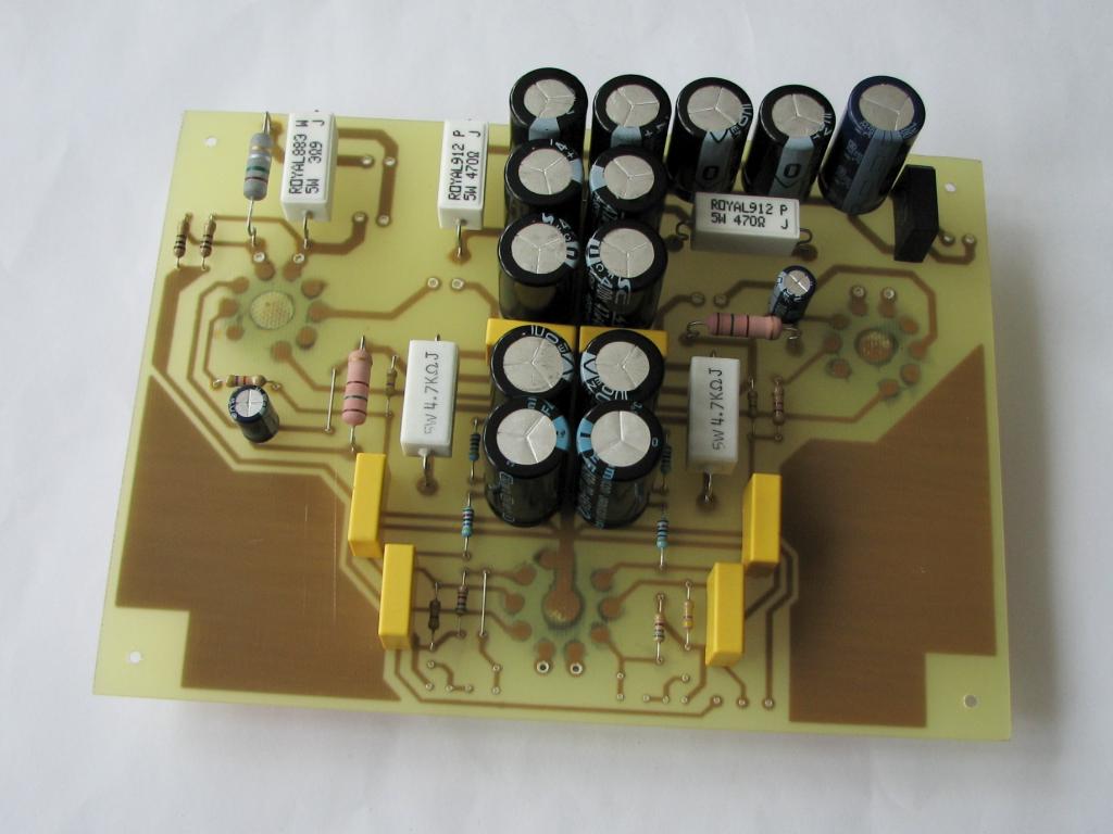
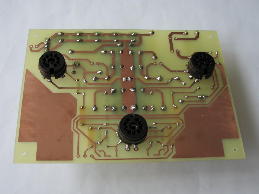
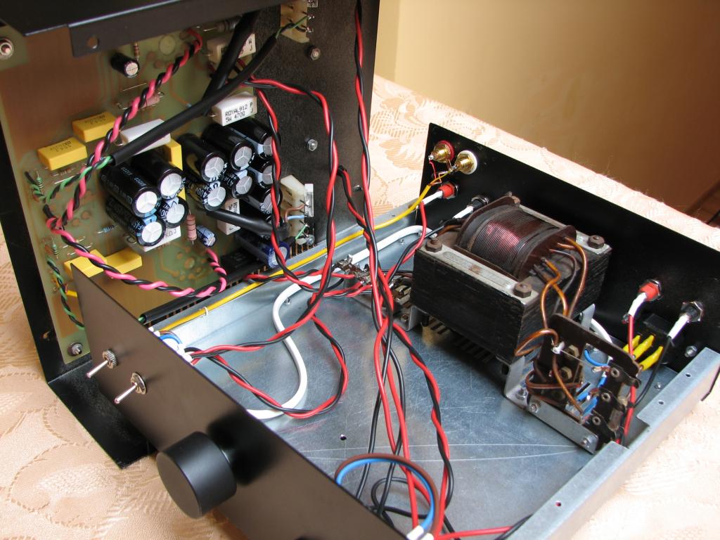
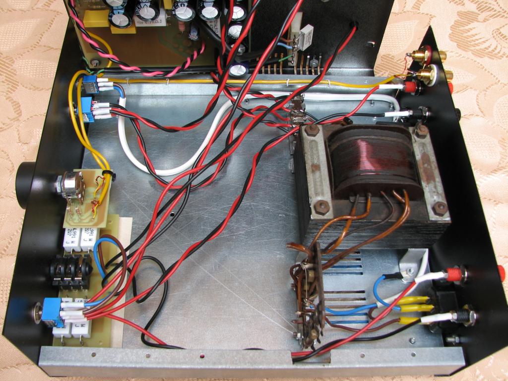
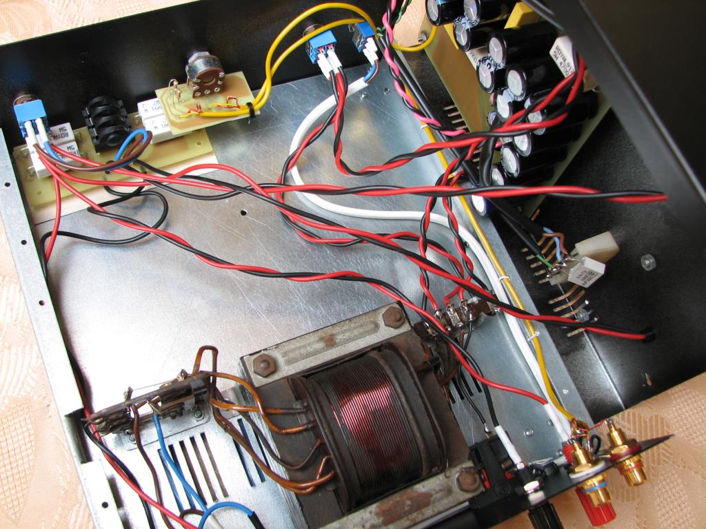
Assembly:
Assembly and location of each components were showed in the pictures below. Metal housing T92 was used. The PCBs were covered with a transparent lacquer in spray. Remember that the components should be placed correctly so that evrything fits the housing.
WARNING!
Be careful with this construction, because it involves high voltages, which can be harmful to your health or life!
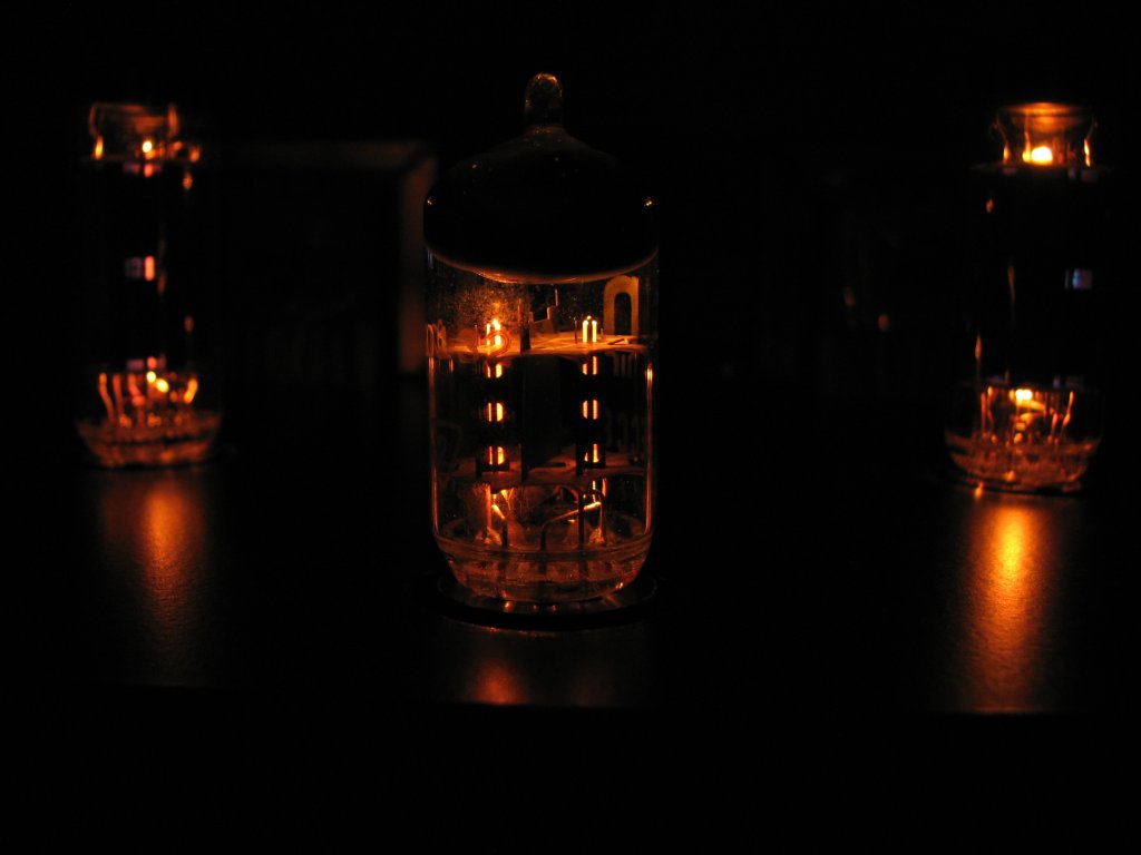
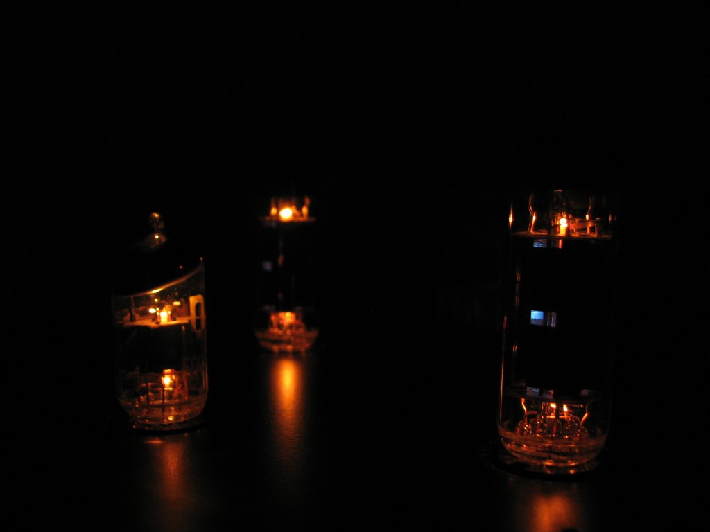
Pictures:


Link to original thread (useful attachment) - Wzmacniacz lampowy stereo