Vermes
Advanced Member level 4

- Joined
- Aug 2, 2011
- Messages
- 1,163
- Helped
- 0
- Reputation
- 0
- Reaction score
- 0
- Trophy points
- 1,316
- Activity points
- 22,318

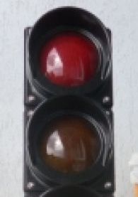
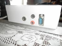
It is a light start indication similar to traffic lights. This device can be used in car racing for starting the competitors. It was equipped with RS232 interface and one input for connecting a photo-barrier which is used to place the competitors in the start line.
The principle of operation is simple. In the moment of “breaking” the barrier on the photo cell connected to the indicator, orange light is displayed, next to red one. The measuring equipment sends information in order to switch on the adequate color.
Commands that control the indicator:
- 0 – turn off all the lights
- 1 – turn on the red light
- 2 – turn on the orange light (1)
- 4 – turn on the orange light (2)
- 8 – turn on the orange light (3)
- 16 – turn on the green light
- 254 - lock the photo barrier, turn off the lights
- 255 – unlock the photo barrier

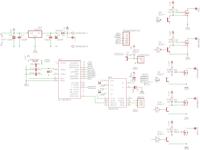
There is a mistake in the schematic, because the emitter of transistor Q7 is not connected to port D4, but to port D3. Transistors that control LEDs are directly controlled by the microcontroller, and not by control transistors as it is shown in the schematic.
Every time you turn on or reset the indicator by switching the button on the wall of the housing, a test is started (video shown in the original thread).
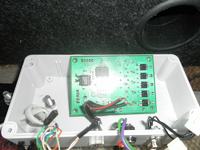
The whole device thanks to using the LEDs is powered from the mains power supply 12DC with an current efficiency 200mA.
Pictures:


Link to original thread - Sygnalizator świetlny/ choinka startowa