Vermes
Advanced Member level 4

- Joined
- Aug 2, 2011
- Messages
- 1,163
- Helped
- 0
- Reputation
- 0
- Reaction score
- 0
- Trophy points
- 1,316
- Activity points
- 22,318
Steropes:
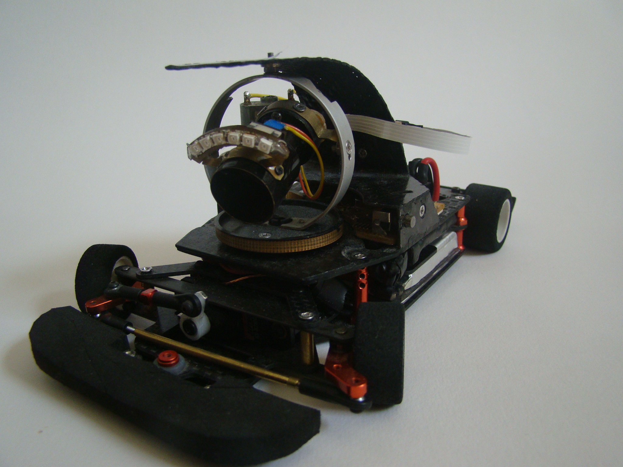
It is a linefollower robot. The main assumption of this device was to create a robot that can see the lines in front of it, to gain more time for reaction. Drive base was made of used RC car model in scale 1/24 Sarpent S240. That limits the maneuverability of the robot, but facilitates the control and gives the chance for real use of the idea in a larger scale beyond the competition.
Camera:
Agile motion around the track requires a quick camera, so that the picture is not blurred, and to have a fresh data about the location. Unfortunately cameras with a large number of frames per second are expensive, and the speed of data given by the matrix is almost impossible to process in real time on board of a small robot. The only possibility is to reduce the number of pixels. Matrix TSL1401R is perfect for this design. It is easy-to-use and have 128 pixels arranged in a single line. The maximum speed of this matrix exceeds the needs of this project, but a quick read-out reduces the signal level at the output, so you have to reduce speed to 1000fps.
One of the problems you can encounter while making this device is the change in the intensity of light falling on the matrix. In the evenings, the intensity of light is so small that you have to provide additional light in front of the robot using LEDs on infrared (IR is the maximum sensitivity of the matrix). On the other hand, on a sunny day, the robot is almost blinded by the light, reading the maximum exposure for all pixels. This problem can be solved by something similar to PWM, during each 1ms the microcontroller performs two read-outs: one with adjustable exposure length and the second – complementary – the values of which are ignored. What can guarantee constant frequency 1000fps? With this solution, on a sunny day you will be able to shorten the exposure time to 40us and get the correct results, and at night, to increase the exposure time to 960us and also see the lines.
Housing for the matrix can be made at home, such as the lens consisting of a single lens. Atmega1284 controls the matrix due to the much of SRAM. Atmega clocks the matrix with a frequency of 5MHz generated by one of the timers. Analog signal is sent from the matrix through operational amplifier to ADC1175CIJM, which is connected in parallel to one of the ports and clocked by the same clock signal. Atmega, after reading the values from the ADC, processes the image. This process occupy about 60% of computing power and the position of line is generated in the form of one or zero byte, which means there is no line in the range. Due to the fact that the robot is not very agile, and the visual field of the camera is only 10cm wide, the camera was mounted on a rotating platform. It causes some complications of the construction, but provides some advantages as well. Firstly – the robot does not always have to be in the line. You can move the camera much faster and more efficiently than the entire robot. With a good algorithm, lines always are in the visual field. The camera is moved by means of the motor via a toothed belt. Ratio is very small – about 1:4. On the axis of the platform there is a potentiometer which reads the position of the camera relative to the robot.
Back of the robot with the image processing system:
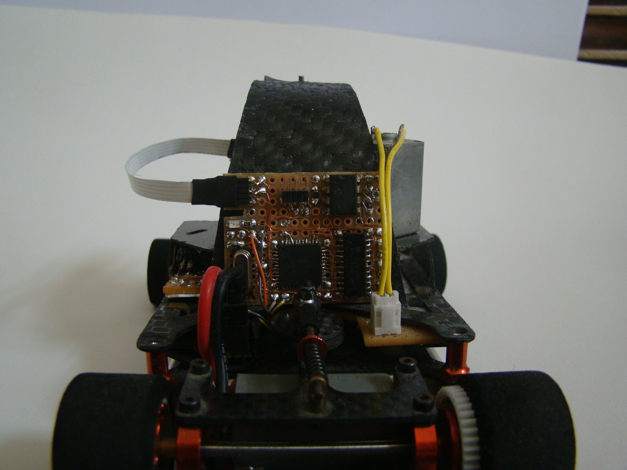
When you want to see the same picture as the robot can see, it can be done using the second UART in Atmega and adapter for USB to create such a possibility. You only have to write a program for visualization in WinApi. The speed of UART does not allow for sending every frame, so the refresh frequency in the computer is only 10fps. Below you can see a sample image (on the top – waveform, on the bottom – gray bar):

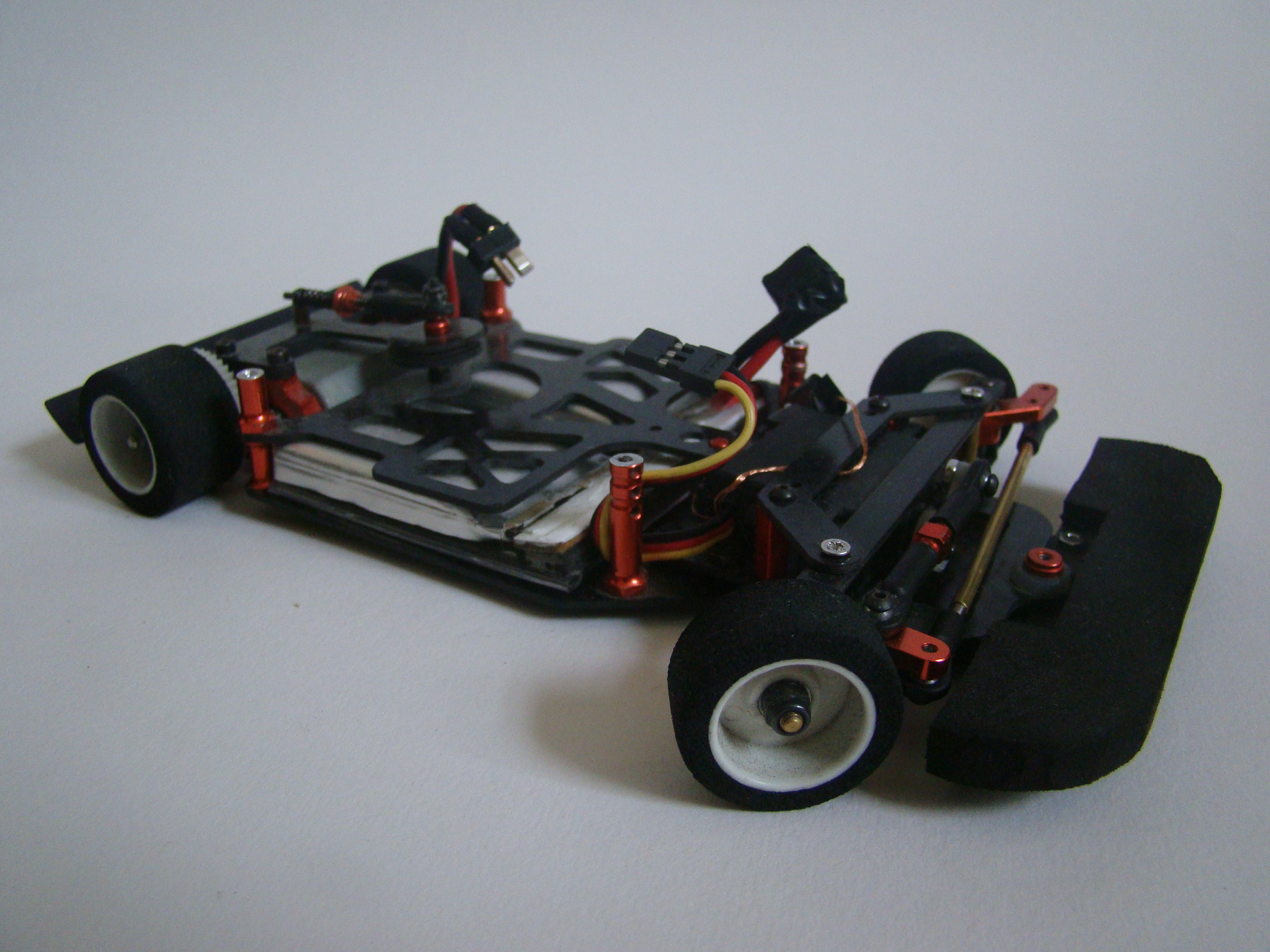
Drive base:
As it was said before, the robot moves on the underbody of the RC Serpent S240. Only the necessary changes were made to the original construction. Bars supporting the bodywork were cut and threaded, so that they could support another layer. The front wheels were put by 1cm to the side, which increased the maximum turn of the wheels. Since the underbody was originally made of carbon fiber, it was good not to change it. The added layer was also made of this material. Two Li-pol cells 800mAh were placed in specially designed for them holder.
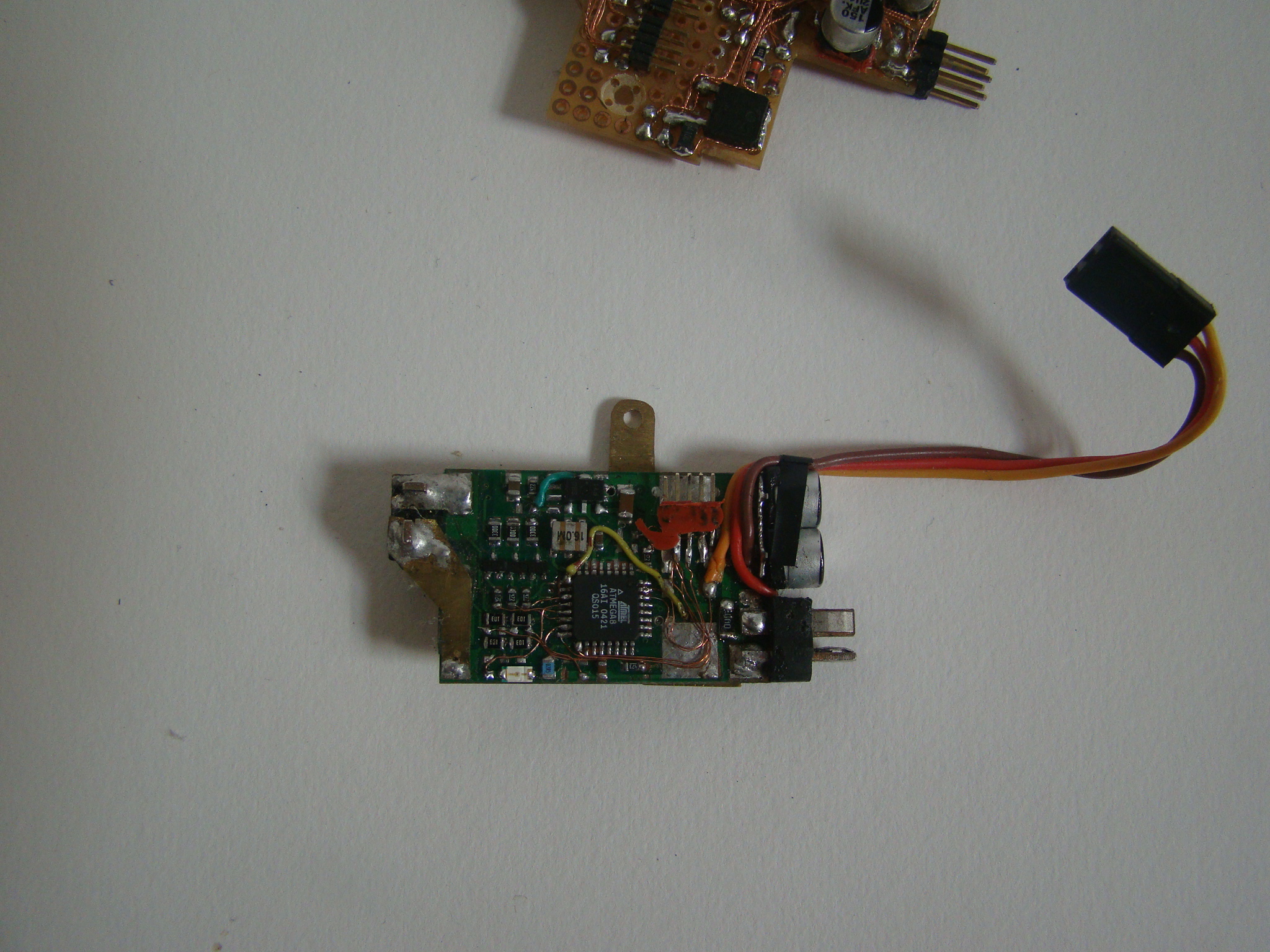
Main engine:
Original brush engine was used for the drive. An old 30A driver for modeling no-brush engines was applied in this device, because it is much cheaper and simpler to process such a driver than buy new components. In the driver there was one channel, form which the MOSFETs were used to connect the rest of electronics. Originally it was intended to mount the encoder on the drive motor, so that you can maintain a constant speed regardless of the change of accumulators' voltage, but it turned out to be impossible due to the lack of space. So, there is an alternative way to do that (the so-called Back EMF Link. It consists of the fact that during normal operation of the engine, it disconnects the power for a moment and measures the voltage produced by the engine, which after stabilization is proportional to the rotation speed. These measurements are carried out by Atmega8 originally installed in the driver. Only the software and few connections were added. Atmega receives the request for the right speed through the UART and thanks to the feedback form the back EMF and PID controller, it obtains the desired speed. Controller board also acts as distributor of the supply and battery control. Atmega8 is permanently connected through economical regulator to the battery and put to sleep. Pressing the button on the side of the robot wakes Atmega, which turns the rest of the electronics by MOSFETs and waits for the first commands for the engine control. Pressing the button again or the battery voltage drop below 6 volts disables the robot and switching Atmega to sleep.
Driver of the main engine:
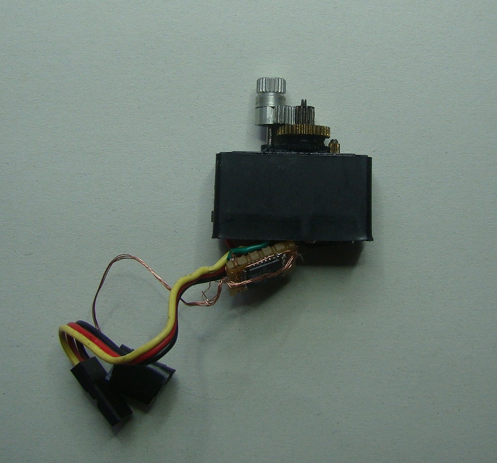
Direction servo:
Originally used servo HS-82mg turned out to be too slow and did not succeed to turn in time. Unfortunately, usually produced servos are not much more quick, so that it is recommended to process the servo. You have to shorten the gears. As a result, you got a very fast servo, but unfortunately the original feedback system does not cope with that change and you have to make your own system. Atmega8 in SMD and Si9986 (1Amper H bridge) formed a new servo controller. PID was implemented and updating the position was speeded from original 50Hz to 200Hz.
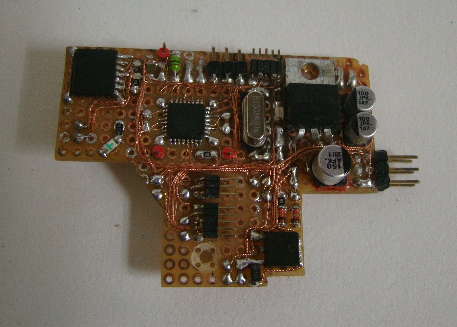
Main board:
Microcontroller responsible for collecting information and distributing commands is Atmega168. It receives commands from the microcontroller of the image and sends the commands on speed and direction. Atmega168 is also responsible for camera rotation engine control and examine of its position.
The main algorithm is to:
- keep the lines in the middle of the field of view
- steer wheels in the direction of the line
- achieve the maximum straight-line speed
- reduce the straight-line speed in proportion to the steering angle, while not below the limit
In the algorithm, there are a few exceptions for sharp corners or momentary loss of line of sight. Most of the factors and parameters of drive can be changed bu the UART. They are stored in the EEPROM of Atmega168 (such as turning circle, maximum and minimum speeds, factor of braking to the corners and others). In total, there are 12 of them and additionally other parameters stored permanently in other microcontrollers. Choosing all the parameters can take a long time and there is room for improvement. The biggest problem is the non-linear relation between speed, braking and driving into corners and others.
Why this robot is based on four microcontrollers instead of one of a greater computing power? It is easier to write a short program for each of the microcontrollers and the time of reaction is shorter as well.
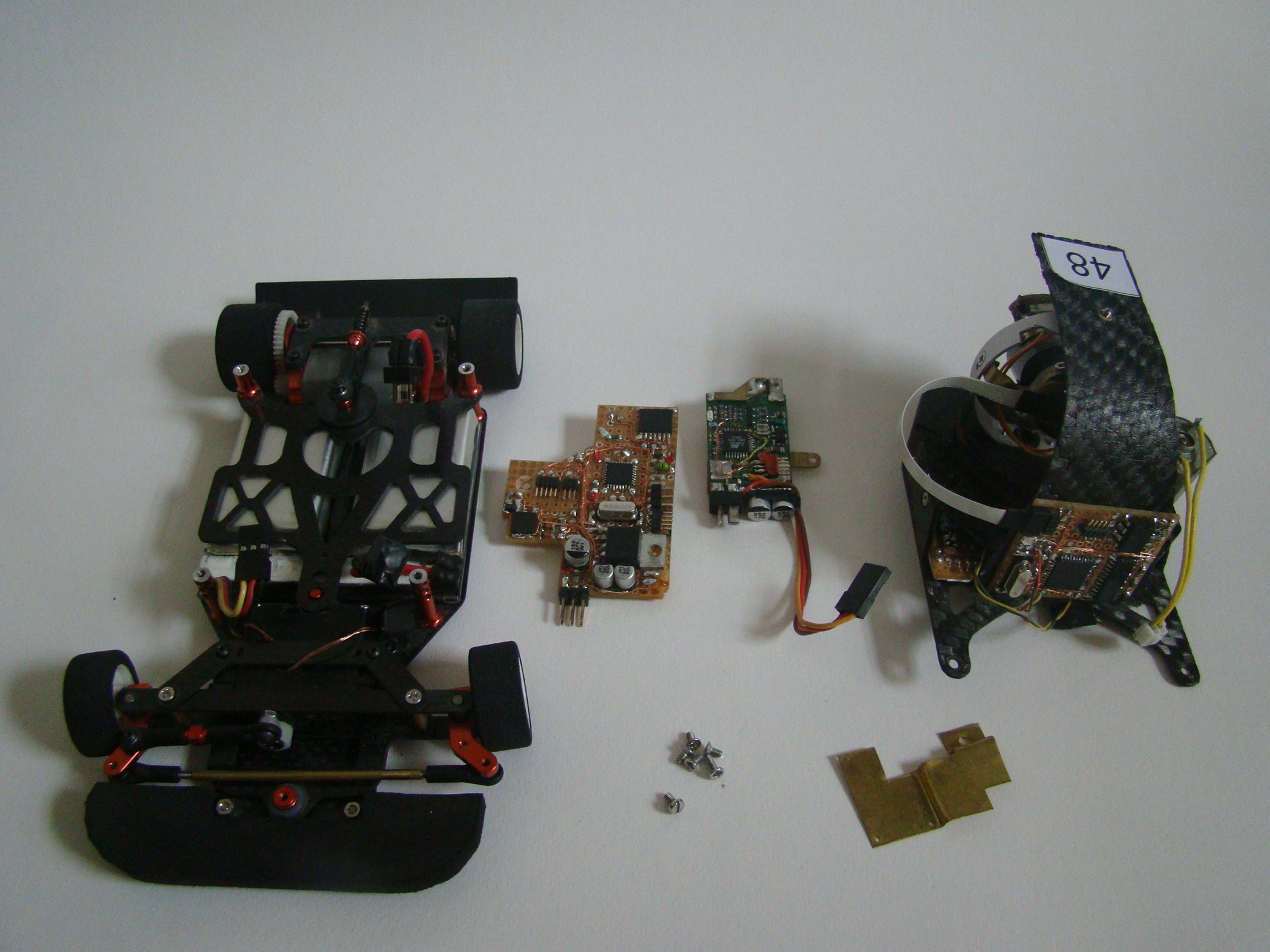
Pictures:


Video:
Link to original thread - Steropes-linefolower inny niż wszystkie