Continue to Site

Welcome to EDAboard.com

Welcome to our site! EDAboard.com is an international Electronics Discussion Forum focused on EDA software, circuits, schematics, books, theory, papers, asic, pld, 8051, DSP, Network, RF, Analog Design, PCB, Service Manuals... and a whole lot more! To participate you need to register. Registration is free. Click here to register now.

Help understanding a circuit

Status
Not open for further replies.

johnkaz77

Junior Member level 1
Joined
Sep 22, 2010
Messages
16
Helped
1
Reputation
2
Reaction score
0
Trophy points
1,281
Activity points
1,396
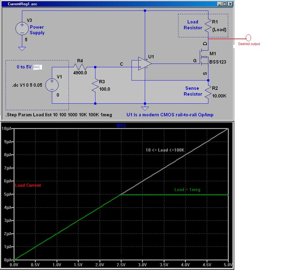
Hello,I found this circuit that should sink 0 to 10uA current.If i got that right,my output must be where the "Load resistor" is,however i don't want my output in series with the power supply (V3),i want to connect the output to a vlsi.If i simply connect a wire to the drain (the red line in the picture), according to Kirchhoff won't this affect my current??
What should i do to get my output? :???:
 

Sorry,i forgot to upload it...
 

Do you intend to remove the load resistor or not?
If you don't, if you make the load resistor much larger than the input impedance of your circuit, then your input current will be the one set by the voltage at the input and the sense resistor. Even better you could replace the load resistor with a current mirror (or even a cascode!) to achieve a high output resistance, if this circuit is on chip.
Have in mind that this circuit can basically provide only an "arbitrarily high" unidirectional current (it can only sink as much current as you want basically, depending on Vin and the sense R). If you want it to source current, that is to draw current out of it, then your load resistor (or current mirror) should be able to provide at least that much current.
Finally, have in mind that whatever connects to the drain, must generate a high enough voltage to saturate the MOS transistor. For example, if you connect a 100Ω resistor and your output current is 1mA, this is never gonna work, since 100mV are not enough to keep the circuit in saturation.
 

Each real current source has limited voltage compliance. The present design can only work on a load with a positive voltage offset to ground, it must not necessarily be the same supply.

Your load must however create a current path to the ground node and apply an offset/bias voltage in the suitable range. A ground refernced load would imply a negative current sink supply voltage. Specify your requirements first and modify the current source respectively.
 

Status
Not open for further replies.

Similar threads

Part and Inventory Search

Welcome to EDABoard.com

Sponsor

Back
Top