Continue to Site

Welcome to EDAboard.com

Welcome to our site! EDAboard.com is an international Electronics Discussion Forum focused on EDA software, circuits, schematics, books, theory, papers, asic, pld, 8051, DSP, Network, RF, Analog Design, PCB, Service Manuals... and a whole lot more! To participate you need to register. Registration is free. Click here to register now.

Help simulating ARF475FL PA

Status
Not open for further replies.

mtwieg

Advanced Member level 6
Joined
Jan 20, 2011
Messages
3,835
Helped
1,310
Reputation
2,626
Reaction score
1,405
Trophy points
1,393
Activity points
29,371
I'm trying to simulate a 128MHz 900W class AB PA described in this application note (and also the **broken link removed**). The only model microsemi gives for the device is a SPICE subcircuit based on a DMOS model, so I'm working with that in LTspice.


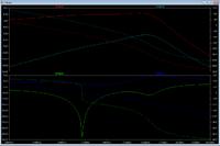
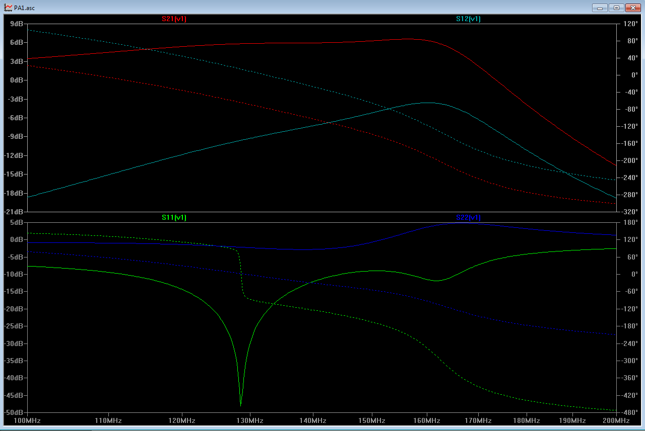
As shown above, I'm able to get a S11 match on the input by following the described tuning procedure, but something is wrong. My S21 is only around 6dB and my |S22| is greater than unity (though strangely I haven't seen any instability during transient simulations). S12 is also very poor. I'm pretty sure my simulation doesn't leave out anything important, but no amount of adjustment to the design parameters seems to solve these issues. I feel I'm either modelling the TLTs wrong, or there's something wrong with the device model itself (when I simulate its characteristic curves they come out pretty different from those in the datasheet).

Here is a pdf schematic of the simulation schematic, and a zip files with all the simulation files. Any help would be appreciated.

View attachment PA1.pdf

View attachment arf475 PA.zip
 

How do you expect the instability by transient simulation ?? It's not seen..
 

I presumed |S22|>1 implied instability?
 

I presumed |S22|>1 implied instability?
Most probably yes.You should check stability circles to be sure..
If you able to use a more convenient simulator like ADS,AWR etc. you can see the issues and the design will be more accurate and easier.
For instance, you may request a evaluation license for 30 days from AWR..
 

I've already used evaluation licenses from AWR a few times, haven't been able to get any more...

Is there any reason to believe LTspice isn't capable of reasonable results?
 

I've already used evaluation licenses from AWR a few times, haven't been able to get any more...

Is there any reason to believe LTspice isn't capable of reasonable results?
ure..
LTSpice is a transient simulator and you cannot see everything with it.
PA designing is a serious task.You should know all characteristics of the PA including stability,input and output impedances,Optimum Load Impedance !! This is extremely important.
Harmonics, IMx curves, PAE, even EVM and ACPR.. there are many specification to be considered..
What can you do with a free single transient or spice simulator ??..
For AWR, look at the internet...;-) I'm sure you will find something...
 

ure..
LTSpice is a transient simulator and you cannot see everything with it.
PA designing is a serious task.You should know all characteristics of the PA including stability,input and output impedances,Optimum Load Impedance !! This is extremely important.
Harmonics, IMx curves, PAE, even EVM and ACPR.. there are many specification to be considered..
This would be reasonable if I were designing from scratch, but I'm not. I'm just trying to duplicate a reference design, and verify that it works reasonable well. I don't need to "see everything." The documentation even gives the optimum load impedance, and as far as I can tell I've implemented it correctly.
What can you do with a free single transient or spice simulator ??..
The only model available for the device is a spice model, so I'm stuck with spice. LTspice isn't developed specifically for RF, but doing simple s-parameter simulation should be trivial. Even if I wanted to do more in depth analysis, it's just a matter of developing the simulation parameters and doing some post processing myself, not the end of the world.
 
Last edited:

LTSpice should be fine for a simple 2 transistor circuit, if the model of the transistor is ok. I don't think the engine software of Cadence for example, when is dealing with the same spice model of the transistor is doing something very different in a transient simulation.
First of all have to check if the model of ARF475FL is working fine with your simulator. I would recommend to replace the complex output balun with a very simple one. Just a transformer balun, and check if you can get at least the linear gain (~15dB). If the gain is fine you can replace the transformer and play with the complex one.
For high-power MOSFET PA is better to use coaxial baluns as in the example below which is using a similar transistor from Freescale:
https://www.qsl.net/f1jrd/MRFE6VP61K25H.html
 
  • Like
Reactions: mtwieg

    mtwieg

    Points: 2
    Helpful Answer Positive Rating
First of all have to check if the model of ARF475FL is working fine with your simulator. I would recommend to replace the complex output balun with a very simple one. Just a transformer balun, and check if you can get at least the linear gain (~15dB). If the gain is fine you can replace the transformer and play with the complex one.
I did this, and still have basically the same performance. I also verified that I had the optimal drain-to-drain load impedance (10+j20), both with the coaxial and transformer output networks (but this seems far from a conjugate match). I don't think my biasing is the issue either, I'm biasing for Id=100mA, which is the maximum recommended in the documentation.

One thing that struck me as odd is that the documentation for the demo circuit shows increasing gain with increased power, which seems very strange for a class AB amp. I don't see that in my simulations either (that's why I originally tried transient simulation; to see if I got higher gain with higher input power, but it never happened).

- - - Updated - - -

For high-power MOSFET PA is better to use coaxial baluns as in the example below which is using a similar transistor from Freescale:
https://www.qsl.net/f1jrd/MRFE6VP61K25H.html
Also I'm very impressed that a class AB amp was able to exceed the theoretical efficiency limit for class B amplifiers.....
 

Increasing gain with increasing power sometimes happen in AB class power amplifiers, because in AB class the conduction angle depends by input power. The phenomenon it is named, Gain Expansion, and this is dependable by multiple factors as, Icq quiescent current, AM-AM and AM-PM interaction. Usually gain expansion happen few dB's back-off from P1dB of the PA.
The theoretical maximum efficiency of Class-B is 78.5%, when Class-AB is somewhere between 50% and 78.5%. So, they can be equal at some point.

You replaced the output balun with a transformer, but what about input? Linear gain of the amplifier depends also by the input match, balance, phasing, etc.
If you cannot reach the 15dB gain (with low input power) with none of the configurations, maybe is something wrong with the spice model.
 
  • Like
Reactions: mtwieg

    mtwieg

    Points: 2
    Helpful Answer Positive Rating
Increasing gain with increasing power sometimes happen in AB class power amplifiers, because in AB class the conduction angle depends by input power. The phenomenon it is named, Gain Expansion, and this is dependable by multiple factors as, Icq quiescent current, AM-AM and AM-PM interaction. Usually gain expansion happen few dB's back-off from P1dB of the PA.
Still hard for me to see how gain can increase as conduction angle decreases, as it will with a class AB as input power goes up.
The theoretical maximum efficiency of Class-B is 78.5%, when Class-AB is somewhere between 50% and 78.5%. So, they can be equal at some point.
Yeah, but that page claims efficiency around 80%. I'm assuming that there's either significant measurement error somewhere, or the amplifier is acting more like a class E.

You replaced the output balun with a transformer, but what about input? Linear gain of the amplifier depends also by the input match, balance, phasing, etc.
If you cannot reach the 15dB gain (with low input power) with none of the configurations, maybe is something wrong with the spice model.
On the input I've still been using the transmission lines and coax balun models. They are basically lossless (except for the 7.3ohm damping resistors), and my S11 is always -20dB or better, so I presume that one way or another my input power is reaching the inputs of the FETs. And yes I get good phase and amplitude balance on the two gates. I can try replacing them with simpler baluns though.
 

Status
Not open for further replies.

Part and Inventory Search

Welcome to EDABoard.com

Sponsor

Back
Top