Continue to Site

Welcome to EDAboard.com

Welcome to our site! EDAboard.com is an international Electronics Discussion Forum focused on EDA software, circuits, schematics, books, theory, papers, asic, pld, 8051, DSP, Network, RF, Analog Design, PCB, Service Manuals... and a whole lot more! To participate you need to register. Registration is free. Click here to register now.

Help in current detection

Status
Not open for further replies.

Amit Dalmia

Newbie level 6
Joined
May 25, 2012
Messages
12
Helped
0
Reputation
0
Reaction score
0
Trophy points
1,281
Activity points
1,402
Hi,
I am a third year undergrad Mechanical Engineer asked to design a circuit where I can detect absence or presence of current and transmit that information wirelessly to some system where one can find see if that circuit has current or not. Sorry if I have posted in wrong thread.
You can consider the problem like this:
There is a simple circuit with only one miniature battery. So, some current is flowing in it. Now, I need to use a device(size order is of mms because it the whole circuit is embedded in plastic material) which is also within the circuit but it is detecting current while it is flowing.
Proceeding further, lets say that the wire gets cut off and hence, current dies. Now, the detector should detect that and transmit that information to some reader or receiver which is placed at a distance of say, 10 metres.
I know that there are a lot of devices which are in use for that but I don't have much knowledge to find which one would be fit to use. Hope that the problem I described was under stable. Please send me a message or drop me a mail at amityy1185@gmail.com if you want further clarifications.
Waiting for an early reply,
Amit Dalmia
 

which type of current you want to sense AC or DC??

other thing doyou want send values of current or just want to know that current is present or not in that particular loop or some hardware??
 

which type of current you want to sense AC or DC??

other thing doyou want send values of current or just want to know that current is present or not in that particular loop or some hardware??

DC it is.
Only current detection in terms of presence and absence would do. No need of getting its magnitude
Thanks
 

a) Do you have an idea of how much current flows (maximum and minimum) in normal use?

b) Can you in some way "tamper" the existing circuit (example: inserting a connection between the battery and the circuit it feeds)?
 

Is this for paicemaker ? I just asking?


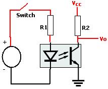
You can use optocoupler to detect current flow, or something similar like this if you whant to measure :

413_circuit_1.jpg
 

For the above questions,
a) No, I don't have idea of how much current would be flowing but it shud be in orders of m-A as per demand of the problem
b) Any tampering could be done as long as it helps in sensing if current is flowing or not and then transmitting it
c) No, this is not for pacemaker. It would be employed for wear monitoring purposes in mineral processing screens.
Thanks
 

I suggest you put a diode between the battery and the equipment it feeds. The diode will have around 0.7V voltage drop when a current goes trough it, no voltage drop at all if no current flows. Does this 0.7V voltage drop affect the existing circuit or is it OK?
 

The situation is like this:
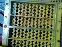
As you can see in the attached images, there are screens having numerous apertures. In industries, these screens are used for mineral processing and are often kept in stacks of say, 20 ft by 8 ft. Each screen itself is around say 1.5 ft* 1.5 ft. Now, in due course of time, screen's aperture size increases and it hurts the industries. The wear is of the order of say, 1-2 mm from edges.
To prevent oversize material being screened, we are trying to embedd a simple circuit in some areas of screen around the aperture perimeter at a distance 1 mm from edges so that when wearing gets to that circuit then, after they get cut out due to pounding of rocks, distinction could be made that - Ok, this screen's current detector is not showing current and hence, it has wore down. I am also thinking of embedding a miniature battery in the screen to supply the power. Hope the situation is more clear now.
 

Simply use optocoupler to sense current in circuit nothing else. Logic output from optocoupler connect to RF transmiter or led or some other notifying circuits.
 

Ok, its fine to embedd a diode. But how do, I get to know if current is flowing or not? I mean, if current stops flowing after wire gets cut down by wearing, how would i be knowing?
I visualized the system like this:
If the current is flowing, that "hardware" is transmitting that information to a reader placed remotely say, 20 metres away
If it stops working, the reader identifies that ok, this particular "hardware" with this unique "id" is not working.
Please tell if i should explain more

If I am picturing the thing correctly, you want to attach to each screen one wireless transmitter to send the information to a point 20 meters away. Am I right?
 

The circuit to embed would be a simple thin wire...
If the wire breaks, then you know the screen has worn out.

You'll know when the wire breaks because it will pass no current.
You could use a simple circuit to sound an alarm or light an indicator, or transmit a signal or anything else..
and the cct could be embedded too.
 

If I am picturing the thing correctly, you want to attach to each screen one wireless transmitter to send the information to a point 20 meters away. Am I right?

Yes, that is right. I want to embedd a simple circuit around the screen with detector and send the information of current's presence or absence 20 metres away.

---------- Post added at 06:17 ---------- Previous post was at 06:04 ----------

The circuit to embed would be a simple thin wire...
If the wire breaks, then you know the screen has worn out.

You'll know when the wire breaks because it will pass no current.
You could use a simple circuit to sound an alarm or light an indicator, or transmit a signal or anything else..
and the cct could be embedded too.

See, installing an alarm is not an option because of the tremendous noise which is present due to pounding of rocks over the screen nor having a light indicator because in some cases, the screens are placed in such a way that you can't see them directly.
The option which looks feasible to me is that there is some detector placed in circuit which detects the current and transmit that info wirelessly.

---------- Post added at 06:17 ---------- Previous post was at 06:17 ----------

The circuit to embed would be a simple thin wire...
If the wire breaks, then you know the screen has worn out.

You'll know when the wire breaks because it will pass no current.
You could use a simple circuit to sound an alarm or light an indicator, or transmit a signal or anything else..
and the cct could be embedded too.

See, installing an alarm is not an option because of the tremendous noise which is present due to pounding of rocks over the screen nor having a light indicator because in some cases, the screens are placed in such a way that you can't see them directly.
The option which looks feasible to me is that there is some detector placed in circuit which detects the current and transmit that info wirelessly.

---------- Post added at 06:18 ---------- Previous post was at 06:17 ----------

The circuit to embed would be a simple thin wire...
If the wire breaks, then you know the screen has worn out.

You'll know when the wire breaks because it will pass no current.
You could use a simple circuit to sound an alarm or light an indicator, or transmit a signal or anything else..
and the cct could be embedded too.

See, installing an alarm is not an option because of the tremendous noise which is present due to pounding of rocks over the screen nor having a light indicator because in some cases, the screens are placed in such a way that you can't see them directly.
The option which looks feasible to me is that there is some detector placed in circuit which detects the current and transmit that info wirelessly.
 

Right.. my point was, it's not really a "current detector", more just a wire that will form part of your circuit.
You just need a transmitter circuit which is normally off, but when a wire in the circuit is broken, you wish the transmitter to turn on.

You could use a transmitter like**broken link removed** as an example.
You'd need a circuit which sends power to the module when the wire breaks, and that circuit could be a MOSFET switch. For an example, see the first diagram here. Replace S1 with a resistor (e.g. 10Mohm), and replace the R1 with your wire. Your transmitter module would be where R2 and D1 are. You may also wish to send pulses instead of a contunuous RF signal, so you'd also need an oscillator, maybe based on a 555 circuit.

Thanks for the help!
I was wondering if we can have a system where the transmitter remains "on" while current is flowing. Now, if we wish to check its status, it will reply back with affirmative when it is "on" or working. If current is cut out, then, we won't be getting any reply from transmitter which would infer that screen has worn out.
Is it possible to do?
 

I think you're saying that you want an indication that the transmitter is ok.
You could achieve that by connecting a battery directly to the transmitter. The transmitter has three pins - GND, +ve and INPUT.
Connect a 555 circuit to the INPUT pin. See here for a circuit. You want to use the 'astable' circuit on that page. This circuit generates pulses.
Now the circuit is continuously sending RF pulses, so you know that the transmitter is ok.
You could get a resistor (lets call it R3) and place it in parallel with R1 in that astable circuit.
Your detection wire would form part of this new resistor connection.
It will change the frequency of the pulses. If the wire breaks, then effectively R3 becomes
disconnected, and the frequency changes.
So, you have an indication that the transmitter is ok (if the transmitter fails, you will
get no pulses), and you have an indication that the wire is ok (if the wire fails, you will
get a different rate of pulses).

The thing you need to concern yourself with is power consumption; are the screens intended to last for hours or days or weeks?
If you're transmitting pulses rapidly, then the battery will not last long.
You may wish to transmit (say) a short train of pulses every 60 seconds, or every 5 minutes.
That is a more sophisticated circuit. At least the simple 555 and transmitter circuit is a 'proof-of-concept'.
The more sophisticated circuit would need to be designed to consume less power when it is not
transmitting, and transmit less frequently.
 
Last edited:
Thanks for the help!
I was wondering if we can have a system where the transmitter remains "on" while current is flowing. Now, if we wish to check its status, it will reply back with affirmative when it is "on" or working. If current is cut out, then, we won't be getting any reply from transmitter which would infer that screen has worn out.
Is it possible to do?


Yes, perfectly possible.

Do some googling about "wireless sensor networks". Probably something aroung ZigBee technology would fit your purposes.
 

I think you're saying that you want an indication that the transmitter is ok.
You could achieve that by connecting a battery directly to the transmitter. The transmitter has three pins - GND, +ve and INPUT.
Connect a 555 circuit to the INPUT pin. See **broken link removed**for a circuit. You want to use the 'astable' circuit on that page. This circuit generates pulses.
Now the circuit is continuously sending RF pulses, so you know that the transmitter is ok.
You could get a resistor (lets call it R3) and place it in parallel with R1 in that astable circuit.
Your detection wire would form part of this new resistor connection.
It will change the frequency of the pulses. If the wire breaks, then effectively R3 becomes
disconnected, and the frequency changes.
So, you have an indication that the transmitter is ok (if the transmitter fails, you will
get no pulses), and you have an indication that the wire is ok (if the wire fails, you will
get a different rate of pulses).

Yeah! Thanks! Looks like it can be proceeded with.
One thing though. Please suggest the type of receiver which have to be used to read those pulses. Also, there are like 20 different screens in an arrangement. What should be done to uniquely give each transmitter an id or something and then read the status of all the transmitters from one reader/receiver?
 

Status
Not open for further replies.

Similar threads

Part and Inventory Search

Welcome to EDABoard.com

Sponsor

Back
Top