Continue to Site

Welcome to EDAboard.com

Welcome to our site! EDAboard.com is an international Electronics Discussion Forum focused on EDA software, circuits, schematics, books, theory, papers, asic, pld, 8051, DSP, Network, RF, Analog Design, PCB, Service Manuals... and a whole lot more! To participate you need to register. Registration is free. Click here to register now.

Having trouble making a Xenon Ignitor

Status
Not open for further replies.
The schematic shows the "bobina" as though it were a coil or transformer. I'm not sure I can see the coil. It looks like you have a triangular piece of metal with a short piece of coaxial cable connected to it. But, there is also something white between the cable and the triangular piece. What is the white thing? Can you get a close-up photo?

An important test you can perform is this; see if the material of the disk is magnetic. If it isn't, then it isn't ferrite.

I've attached a couple of pictures of a piezoelectric ultrasonic transducer. You'll notice how much it looks like what you have. The silver coating on the flat surfaces is an electrode. I've soldered a couple of wires to mine.

- - - Updated - - -


I notice that the schematic shows a couple of 20 kilovolt capacitors; can you post a picture of those capacitors?


Actually this piece of metal is sandwiched between two these circular discs,ill give the pic tomorrow morning.Our system works even if we have one circular disc i don't have any picture of the capacitor as it is moulded.It is not magnetic,so its not ferrite.Its some kind of stone when we break it its like a ferrite but ferrite cannot be coated by any material on top.Do let me know if you require any other information.

Regards,
 

When the two discs are put together with the metal sandwiched between, what happens to the two silvered faces that are on the outside of the sandwich?

I believe the two discs are made of some dielectric material such as barium titanate. One disc then can act as a very high voltage capacitor; two discs sandwiched together will act as two capacitors in parallel IF the two metal surfaces (electrodes) on the outside of the sandwich are connected together and possibly grounded somewhere.

The two capacitors C5 and C6 are rated at 20 kV, so the transformer TA must be putting out somewhat less than that, perhaps 10 kV. The coil CH appears to function as another step up transformer, so the voltage at its top will be the 10 kV multiplied by some further amount. Maybe the voltage at the top of CH is 30 or more kilovolts, and the two discs are a very high voltage capacitor not shown as such on the schematic.

If you have a capacitance meter, try measuring the capacitance between the two silver faces of one of the discs.


Dear Friend,

PLease refer to the ckt diagram in my prevoius posts,its not connected to gnd but connected to spark gaps and other things.


BR,

Pranay
 

Dear Friend,

PLease refer to the ckt diagram in my prevoius posts,its not connected to gnd but connected to spark gaps and other things.


BR,

Pranay

Yes, I understand what you have shown so far.

In the real circuit, the two discs are sandwiched and there is a triangluar piece (of metal?) between the discs. But, are the outside silver surfaces connected to anything at all, or they just floating?

Please PRETEND that the two discs are capacitors and post a schematic showing where those two capacitors are connected in the circuit.
 

In the circuit diagram, the bobina (CH) has 3 connections. I only see 1 wire connected to the thing in the photos. Something is missing.
 

In the circuit diagram, the bobina (CH) has 3 connections. I only see 1 wire connected to the thing in the photos. Something is missing.

There are a few things about the given circuit that are puzzling to me. The full lamp current has to pass through the high voltage winding of the "bobina". You would normally think that a high voltage winding would consist of a lot of turns of small wire.

I worked on 2.5 kW xenon lamps in the military, and the characteristics of those lamps were reminiscent of most gas discharge lamps. Once the arc is struck, the lamp impedance drops precipitously. The voltage drop across our lamps was about 25 volts when carrying 100 amps. The lamp in the OP's circuit is connected directly across the 220 VAC line when it strikes. If this were done with most high pressure xenon lamps I'm familiar with, there would be a big explosion when the near short circuit of the lamp was connected to the 220 VAC grid.

I suppose it's possible the OP's lamp is a small, low pressure lamp. But, there's still no current limiting means in series with the lamp other than the resistance of the "bobina" winding. Maybe that's enough.


Dear Sir,

This is just a Ignitor circuit to give a boost up to break the gas discharge and it is only active for a flash of a second and after that we our current controller mechanism come into play .This is just an ignotor rest we have our own circuit which is quite reliable.

- - - Updated - - -

Dear Sir,

Rest two are connected a sshown in the circuit diagramm,the wire coming out is connected to the spark gap and one end of the coil is connected to the lamp positive and the other to capacitance c2 which is connected to the ground.
 

Are you still seeking advice here on the forum?

I believe you were originally asking about the "bobina", and you wanted to know what the function of the two dark colored discs with the silvering on the flat faces is.

Are you still trying to determine these things?

If so, perhaps you could answer the question i posed in an earlier thread:

"In the real circuit, the two discs are sandwiched and there is a triangluar piece (of metal?) between the discs. But, are the outside silver surfaces connected to anything at all, or they just floating?

Please PRETEND that the two discs are capacitors and post a schematic showing where those two capacitors are connected in the circuit."
 

Dear Sir,

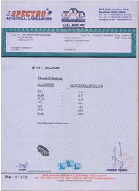
I have got te chemical analyses done for the ferrite like thing,please find the report attached,kindly suggest me suitable materials for this inductance.


if a VDR was connected from the output side of the spark gap to the + line, then if the gap fired and flashed the xenon tube and broke down the VDR, then the main current path would be via the VDR. One question how many connections has this "bobina" got?
Frank
 

We have found out that the Bobina is a peizo ceramic with silver plating on both sides.Please suggest from where I can get this peizo ceramic.
 

We have found out that the Bobina is a peizo ceramic with silver plating on both sides.Please suggest from where I can get this peizo ceramic.

Go back and re-read post #22 where I said "I believe the two discs are made of some dielectric material such as barium titanate. One disc then can act as a very high voltage capacitor." I've been trying to tell you that the "bobina" is a capacitor. Go back and re-read my posts, especially where I asked you questions you didn't answer.

Now, you say that it is a "piezo ceramic". If it is just a ceramic material with silvered faces, then it is a capacitor. The word "piezo" changes things. "Piezo" means "pressure". A piezo ceramic is intended to generate a voltage when mechanically stressed. Sometimes they generate a high voltage when mechanically struck, perhaps to ignite the gas in a barbecue grill.

Then can also work in the reverse mode, where when a voltage is applied, they generate a mechanical movement. This is what ultrasonic transducers do. The image I attached to post #19 shows just such an ultrasonic transducer.

In your case there would seem to be no need to generate a voltage pulse when a mechanical impact is applied to the "bobina". At least, you haven't mentioned that an impact is needed to ignite the xenon lamp.

You should connect an LCR meter to the silvered faces of the "bobina" and measure its capacitance. Then you can buy a high voltage capacitor with the correct capacitance and voltage rating.

Here's a company in the U.S. that makes piezo ceramic devices for various purposes:

https://www.americanpiezo.com/standard-products/ultrasonic-cleaning-transducers.html

But if you just need a capacitor (without the piezo property) you might have to look elsewhere.

You could find out if the "bobina" is a "piezo" ceramic by connected the two silvered faces to an oscilloscope and gently tapping the "bobina" on one of the faces to see if a voltage is generated by the mechanical impact (the tapping).

If no voltage is generated, then the ceramic material of the "bobina" is not permanently polarized. A permanently polarized piezo ceramic is an example of an "electret": https://en.wikipedia.org/wiki/Electret

If the "bobina" is not permanently polarized, then it's just a high voltage ceramic capacitor.
 

Status
Not open for further replies.

Part and Inventory Search

Welcome to EDABoard.com

Sponsor

Back
Top