Continue to Site

Welcome to EDAboard.com

Welcome to our site! EDAboard.com is an international Electronics Discussion Forum focused on EDA software, circuits, schematics, books, theory, papers, asic, pld, 8051, DSP, Network, RF, Analog Design, PCB, Service Manuals... and a whole lot more! To participate you need to register. Registration is free. Click here to register now.

[SOLVED] generating high frequency square wave(24~25 MHz)

Status
Not open for further replies.

shubh1994

Member level 1
Joined
Jul 7, 2012
Messages
32
Helped
2
Reputation
4
Reaction score
2
Trophy points
1,288
Activity points
1,540
I have 24 MHz sine wave and i want to convert it in 24MHz square wave , i have tried NAND gate(74lvc10) high speed but it giving same output as input,
i tried schmitt trigger(74lvc14A) even but not able to find the solution Now i am in big trouble,not getting any other way:cry:

So,please please help me out!!!!!!!!
 

It is huge circuit for variable frequency but i need only one high frequency 20MHz to drive the clock of OV7670 camera(XCLK)
 

Where are you getting the sine wave from? I haven't used any Camers but can't the Clk be provided with a quartz circuit?

Edit: Provide the XCLK from crystal or micros oscillator out.
 
Last edited:

can anybody give me information regarding how to use crystal clock oscillator (F1100E) to use TTL output, i tried but again getting sine wave,
plz help!!!!!!!!:-(
Can crystal clock oscillator be damaged ?? or what??

- - - Updated - - -

quartz crystal generates sine wave and i need square wave, i have tried converting sine wave in square wave using 7404(NOT gate) an some resistor but again failed

- - - Updated - - -

I am using ATMEGA32 for this purpose which doesn't have clkout. For clkout i have shift to ATMEGA328 which is not available currently??
 

And how are you checking the waveform?

You need a wide bandwidth oscilloscope and low capacitance probe. Without these, the edges of a square wave will rise slowly and fall slowly making it look far more 'rounded' and similar to a sine wave. Also bear in mind that the OV7670 will respond to any waveform that meets logic high and low levels, it probably isn't too worried what shape the signal is.

Brian.
 

To be able to give any useful guidance, it is important that you describe your setup in more detail.

1) what is your 24mhz signal source specs ? Signal levels, source impedance etc. You need sufficient signal strength to drive the gates.

2) how are you doing this measurement ? Is there much capacitance in your measurement path ? A 1meg probe with 10pF capacitance would act as a LPF !! to be able to "see" a square wave @24MHz you need to be able to pass its harmonics of 24x3, 24x5, 24x7, .... MHz. Can your test setup do this ?

3) Can you post a full schematic, and a jpg of your actual setup would help.
 

And how are you checking the waveform?

You need a wide bandwidth oscilloscope and low capacitance probe. Without these, the edges of a square wave will rise slowly and fall slowly making it look far more 'rounded' and similar to a sine wave.(...)
The previous crystal oscillator thread already suggested a pure measurement problem. I suppose that a 100 MHz oscilloscope with a standard 10:1 passive probe would show that the waveform isn't a sine, but you need 200 MHz or more bandwidth and a proper probe connection to asses the actual waveform.

Without suitable instruments, you still have the option to believe the datasheet specification about crystal oscillator waveform and just use it.
 

@betwixt even sine wave at input of XCLK of OV7670 will work???

- - - Updated - - -

@FVM
I am using 100MHz oscilloscope and not using capacitive probes,currenly using normal probes,can it affect the crystal clock oscillator waveform??
 

With suitable ground connection, a standard 10:1 probe should reproduce the waveform. A 1:1 probe most likely won't due to high input capacitance.
 

@FvM
I have used XTAL2 of microcontroller and connected it three input NAND gate with all ends shorted to XTAL2 but output is coming sine, can u explain how it is happening so????

- - - Updated - - -

@ jayanth
i tried to look for max038 but it seems to very costly inr 800~ 900 in india(of course it will since it provides complete solution to function generator).So, can't we have a cheaper solution for this particular problem
 

I will see if I can find any better device. Meanwhile google and try to find what type of OSC is used for projects using OVAxxxx camera you are using.
 

@shubh1994, what is almost certainly happening is the capacitance of your scope probes is having to be charged up by the rising of the logic level and discharged into the falling edges so the fast edges are slowed down. It isn't possible to completely eliminate that happening but a low capacitance probe will help.

If you do use a low capacitance x10 probe, make sure you adjust it before using it. Apply a low frequency (~1KHz) square wave to it and adjust the compensation capacitor in the probe until it has clean tops and bottoms on the waveform. Most oscilloscopes have a calibration square wave output for this purpose.

And yes, the OV7670 will probably work even with a sine wave clock. Internally it will decide if the clock is high or low based on the absolute voltage it sees so as long as the sine wave goes above the high threshold and below the low threshold it will probably work. The reason for specifying a square wave is it is easier to quantify the high/low ratio.

Brian.
 
@betwixt
I think you have worked on ARDUCAM if so can you please tell me can i interface it to RASPBERRY PI
 

@jayanth
As you told me now I am using atmega168 with 5v supply and 16MHz crystal having following fuse bits
lfuse 0xbf
hfuse 0xdf
efuse 0x00
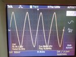
Basically i want to generate a square wave at PB0(clkout) but getting a 16MHz sine wave. I am not getting why this is happening??
please help !!! :
 

Attachments

  • output.jpg
    output.jpg
    1.5 MB · Views: 80

hello,

I don't know AVR, but even with PIC, you can not get a good square signal at so high
frequency, because of internal time response.
What is the load value on the output .. try to use minimum resitor value ( 470 ohms ?) to reduce capacitance effect.
and also Oscilloscope with very large band width...

Is there ,in AVR a similar configuration as on PIC ?
SLRCON=0; // standard rate for PORTA,B,C,D,E
act on speed response..
 

isn't this thread going 'threadbare' now ? and the OP not reading any of the useful responses is just a bit insulting and annoying. Despite the fact he's a 19yr old newbie.
So i'm out. Cheers guys !
 

@kripacharya
Sir,i am responding to every body comments, i am not able to understand why u felt that i am ignoring the solutions provided??
1.I have used
a) F1100E crystal clock oscillator
b) atmega168 clock out
c) used quartz crystal and connected a NOT gate to its output to convert in square wave
but, none of above is working ,every try gives me sine wave

2.I am using 100mhz Tektronix DSO with 10x probes(standard).
 
Last edited:

Status
Not open for further replies.

Similar threads

Part and Inventory Search

Welcome to EDABoard.com

Sponsor

Back
Top