Continue to Site

Welcome to EDAboard.com

Welcome to our site! EDAboard.com is an international Electronics Discussion Forum focused on EDA software, circuits, schematics, books, theory, papers, asic, pld, 8051, DSP, Network, RF, Analog Design, PCB, Service Manuals... and a whole lot more! To participate you need to register. Registration is free. Click here to register now.

Square Wave Generation Error with Stm32

uranyumx

Member level 5
Member level 5
Joined
Mar 5, 2011
Messages
81
Helped
1
Reputation
2
Reaction score
0
Trophy points
1,286
Activity points
1,957
Hello,

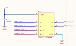
I have tried to generate square wave signals with TMUX1122DGKR switch. Basically, the stm32 feeds two analog signals from its internal DAC, the switch generates square pulses based on SET and RESET commands. But at the output signals, there is an extra 250 mV pulses on the blue signals. I didn't understand why it happened. Do you have any suggestion on that?

Thank you,

Code:
while (1)
  {
    /* USER CODE END WHILE */

    /* USER CODE BEGIN 3 */

      // Stimulation Voltage Signal Generation

      DAC1_Out = DAC1_Buf*(4096)/3.3;
      HAL_DAC_SetValue(&hdac, DAC_CHANNEL_1, DAC_ALIGN_12B_R, DAC1_Out);
      //HAL_Delay(1);
      HAL_DAC_SetValue(&hdac, DAC_CHANNEL_2, DAC_ALIGN_12B_R, DAC1_Out);

      //delay_us(200);
      HAL_GPIO_WritePin(PHASE_SEL_1_GPIO_Port, PHASE_SEL_1_Pin, GPIO_PIN_SET);
      delay_us(200);
      HAL_GPIO_WritePin(PHASE_SEL_1_GPIO_Port, PHASE_SEL_1_Pin, GPIO_PIN_RESET);
      delay_us(100);
      HAL_GPIO_WritePin(PHASE_SEL_2_GPIO_Port, PHASE_SEL_2_Pin, GPIO_PIN_SET);
      delay_us(200);
      HAL_GPIO_WritePin(PHASE_SEL_2_GPIO_Port, PHASE_SEL_2_Pin, GPIO_PIN_RESET);
      delay_us(400);

IMG_3556.jpg
 

doraemon

Super Moderator
Staff member
Advanced Member level 4
Joined
Jun 21, 2009
Messages
1,194
Helped
284
Reputation
576
Reaction score
282
Trophy points
1,363
Location
Japan
Activity points
12,173
Hello!

I don't understand the purpose, but OK, you might have your reasons.
The analog multiplexer has 2 inputs S1, S2, 2 outputs D1, D2, and 2 selections SEL1, SEL2.
When selected, S1 = D1, S2 = D2, which is the signals you observe. But when not selected,
D1 and D2 are connected to nothing, therefore the impedance is high and it can be influenced
by anything, for example if there is another signal in the neighborhood (and there is one).
Try to setup pulldown resistors at the outputs. For example 10k.

Dora.
 

uranyumx

Member level 5
Member level 5
Joined
Mar 5, 2011
Messages
81
Helped
1
Reputation
2
Reaction score
0
Trophy points
1,286
Activity points
1,957
Thank you very much @doraemon for your comments! It was worked with connecting 2 kOhms pull down resistors. So the placing these resistors at the outputs short any unwanted signal on the trace to the ground?

@KlausST , here is the schematic,
 

Attachments

  • 1677257926911.png
    1677257926911.png
    31.8 KB · Views: 20

LaTeX Commands Quick-Menu:

Similar threads

Part and Inventory Search

Welcome to EDABoard.com

Sponsor

Top