Continue to Site

Welcome to EDAboard.com

Welcome to our site! EDAboard.com is an international Electronics Discussion Forum focused on EDA software, circuits, schematics, books, theory, papers, asic, pld, 8051, DSP, Network, RF, Analog Design, PCB, Service Manuals... and a whole lot more! To participate you need to register. Registration is free. Click here to register now.

Fundamental- distortion in Signal measured from a Signal generator through Oscilloscope

Status
Not open for further replies.

blackite

Newbie level 4
Joined
Oct 6, 2021
Messages
7
Helped
0
Reputation
0
Reaction score
0
Trophy points
1
Activity points
58
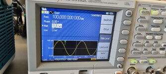
I have a doubt whcih is very fundamental. i wanted to generate a 100mv sinus signal from a signal generator and measure it on an oscilloscope. Actually to do this i attached a two sided BNC cable. The frequency was 100Khz.
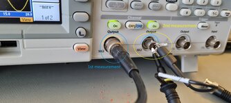
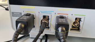
1) First measurement- One side to signal generator and the other side to oscilloscope.
2) A second measurements i did was used one of the oscilloscope probe and directly attached the probe to BNC input port in the signal generator. Please see the picture attached to this thread.
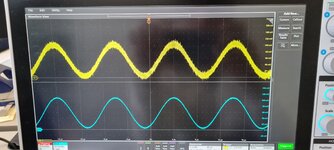
As shown in picture the the oscilloscope signal - blue signal is from the first measurement BNC to BNC and the second measurement is the yellow signal. My question why are there distortions in the second measurement. I assume they are reflections whne i measure directly form the probe and in 2nd measurement the oscilloscope is filtering? But according to my knowledge the oscilloscope should show me the complete bandwidth also when a bnc cable is attached. I want to understand what exactly the oscilloscope is doing here because i want to use the sine wave generated form the SG for one of my projects.
 

Attachments

  • 20211006_140033.jpg
    20211006_140033.jpg
    1.6 MB · Views: 149
  • 20211006_140039.jpg
    20211006_140039.jpg
    1.7 MB · Views: 153
  • 20211006_140107.jpg
    20211006_140107.jpg
    1.5 MB · Views: 143
  • 20211006_140110.jpg
    20211006_140110.jpg
    1.3 MB · Views: 152

Hi,

I call it "noise". Because it looks like a bunch of random frequencies.

* Distortion (harmonic) is usually meant as overtones, which means integer multiple of the fundamental frequency.
* Reflections of a sine shape will still be a sinewave.. with identical frequency. So a reflection of a sinewave will just modify amplitude and phase shift.

Thus I expect it to be noise, maybe caused by HF sources around (cellular phone, Bluetooth, WiFi, switch mode power supplies...)

Klaus
 

Hi,

you are free to use any type of filter to attenuate unwanted frequencies.
So yes, an RC filter is able to attenuate frequencies.

The filter needs to
* pass all frequencies you want to see on the scope
* attenuate the others.

Klaus
 

As a first step, you may want to configure channel bandwidth. The 1.5 GHz oscilloscope is apparently too fast for you.
--- Updated ---

Too much noise bandwidth for a high impedance passive probe.
 
Last edited:

As a fisrt step, you may want to configure channel bandwidth. The 1.5 GHz oscilloscope is apparently too fast for you.
limiting the bandwidth removes higher frequencies but since i want to further use the signal from signal generator for my project i should still use a filter right??
 

The noise isn't present in the generator output as the 50 Ohms direct connection shows, it's generated by the passive high impedance probe (and the oscilloscope input amplifier).
 

The noise isn't present in the generator output as the 50 Ohms direct connection shows, it's generated by the passive high impedance probe (and the oscilloscope input amplifier).
I think you are right. The noise is from the OScilloscope because my bandwidht was set to 1GHz. To test this i measured the voltage output of a 9v battery and observed that it was showing oscillating noisy signal between 8.9v and 9.3v which according to me should not be the case. it should be quite precise. REducing the bandwidth to 20 Mhz did improve the battery signal shown on Oscilloscope and the SG's Sinus signal shown on Oscilloscope. Please correct me if my conclusion is wrong.
 

I would be suspicious that the ground side of the probe is not
a "solid" ground. Maybe probe slip ring at probe for ground clip
dirty. Possibly alligator ground connection to its lead is poor.
Try it on channel 1 of generator, maybe the generator 50 ohm output
has degraded, cracked trace or poor solder connection on its PCB
compromised.

With a 50 ohm source thats quite a lot of noise on signal.

Probe body contact with scope input signal pads dirty .....?


Regards, Dana.
 

@blackite: Your considerations are correct. 20 MHz is an appropriate bandwidth for 100 kHz signal measurements.

@danadakk: You should differentiate between white noise generated by the probe resistors and oscilloscope amplifier and external interference signals (hum, radio transmitters in the vicinity, switching power electronics) that might be injected through a bad ground connection. Here you have only the former.
 

    blackite

    Points: 2
    Helpful Answer Positive Rating
Measurement bandwidth, as reported by blackite, has been 1 GHz. Noise bandwidth has nothing to with signal frequency.
 

I would be suspicious that the ground side of the probe is not
a "solid" ground. Maybe probe slip ring at probe for ground clip
dirty. Possibly alligator ground connection to its lead is poor.
Try it on channel 1 of generator, maybe the generator 50 ohm output
has degraded, cracked trace or poor solder connection on its PCB
compromised.

With a 50 ohm source thats quite a lot of noise on signal.

Probe body contact with scope input signal pads dirty .....?


Regards, Dana.
Probably not because the probe and oscilloscope are relatively new few months old.
 

thank you everyone for your recommendations and suggestions. I learned something new that depending on the frequency of the signal from signal generator i should have a suitable bandwidth set in my oscilloscope otherwise the probe will measure unwanted noise signals.
 

Measurement bandwidth, as reported by blackite, has been 1 GHz. Noise bandwidth has nothing to with signal frequency.
The scope is capable but what is its "auto" selected sampling rate for signal
under examination. 100 Khz signal is not acquired at 1 Ghz unless user overides
acquisition rate.

Noise BW in context of signal determines signal statistical characteristics, like instantaneous frequency.

Regards, Dana.
 

Do you expect that the oscilloscope magically selects and acquisition rate and anti-aliasing filter depending on the signal fundamental frequency and waveform? That doesn't happen. At best the acquisition rate is reduced depending on timebase setting and a preselected acquisition length, but the noise bandwidth is not necessarily reduced by a respective low pass filter, need to check the instrument manual.

With 40 us window, MSO 44 will most likely work at default 6 GS/s sample rate and achieve the specified probe bandwidth of 1 GHz unless you set a reduced channel bandwidth. Effective noise bandwidth will be somewhere between 1.2 and 1.5 GHz, depending on the filter characteristic.

Not "at best", in most scopes its auto, you override to put scope at max sampling rate under
demands you need.

Not being an expert or in possession of hundreds of scopes (although I do have a collection)
I would bet in todays scopes that might be also offered as a user settable default....

1633639571632.png


Interpolation "normally" set to linear automatically by default. Many papers on
web and consult you manual. User "normally" has to pick sin(x) / x. Of course
this is a default, not a signal calculated......condition. Or is it in the latest scopes ?


Regards, Dana.
 
Last edited:

Status
Not open for further replies.

Part and Inventory Search

Welcome to EDABoard.com

Sponsor

Back
Top