eagle1109
Full Member level 6
- Joined
- Nov 20, 2014
- Messages
- 390
- Helped
- 4
- Reputation
- 10
- Reaction score
- 7
- Trophy points
- 1,298
- Location
- Saudi Arabia
- Activity points
- 5,928
Hello,
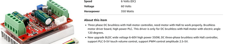
I'm working on this project which is to control a 3ph dc motor using a 3ph dc motor control board:
Note: this picture has been taken before finishing the wiring.


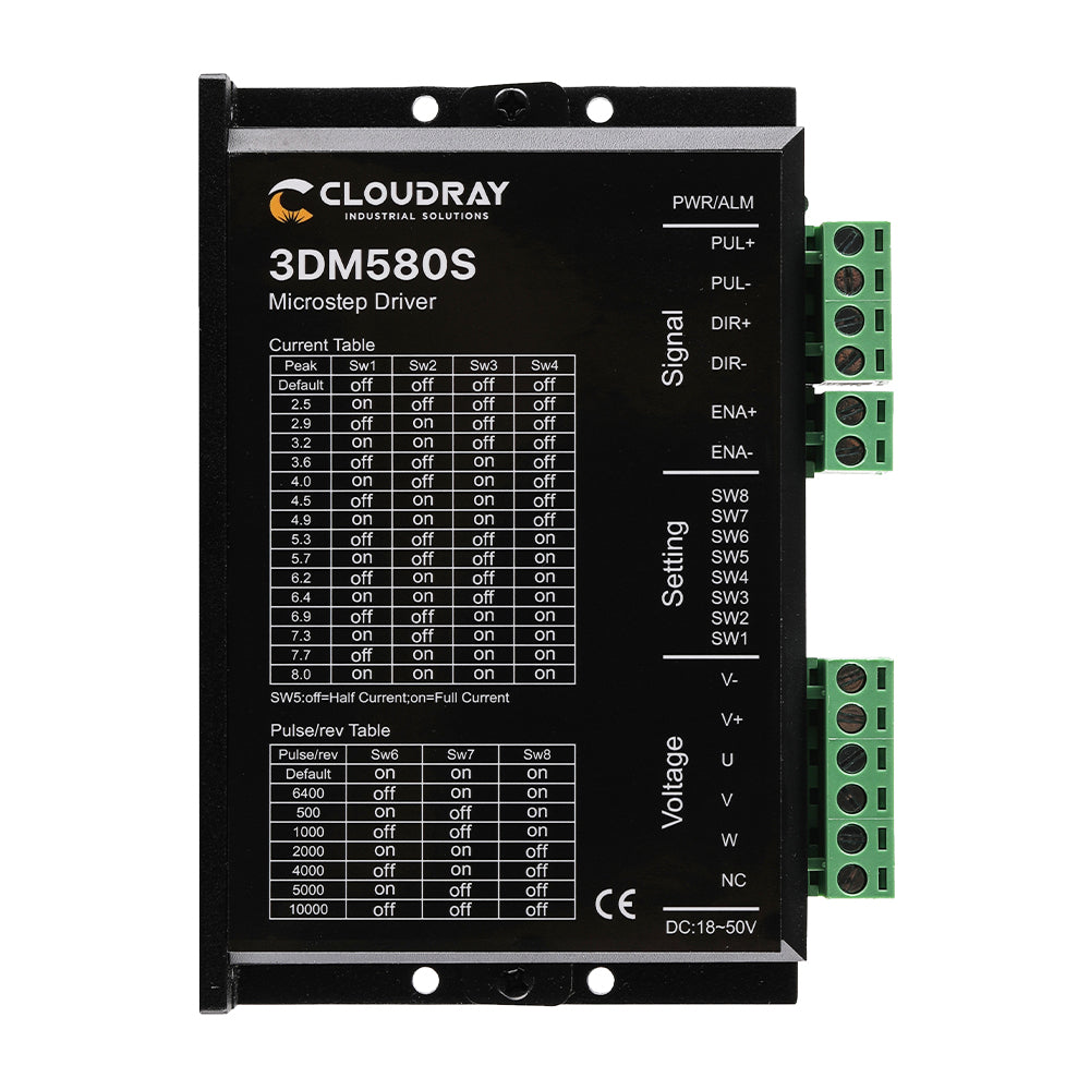
This is the control board layout:

This is how I connected it with the arduino board:

But the problem, first time I tried to pull this line using the arduino, I heard like glitching sound and everything shutdown, the 24V power supply, the controller and the arduino board.
I knew there must be a short pulling this line to 0V, but why?
I forgot add this:
I took pictures for the board, after checking out the pictures, I found that this is a cracked diode.

I'm working on this project which is to control a 3ph dc motor using a 3ph dc motor control board:
Note: this picture has been taken before finishing the wiring.
This is the control board layout:
This is how I connected it with the arduino board:
But the problem, first time I tried to pull this line using the arduino, I heard like glitching sound and everything shutdown, the 24V power supply, the controller and the arduino board.
I knew there must be a short pulling this line to 0V, but why?
--- Updated ---
I forgot add this:
I took pictures for the board, after checking out the pictures, I found that this is a cracked diode.
Last edited: