Continue to Site

Welcome to EDAboard.com

Welcome to our site! EDAboard.com is an international Electronics Discussion Forum focused on EDA software, circuits, schematics, books, theory, papers, asic, pld, 8051, DSP, Network, RF, Analog Design, PCB, Service Manuals... and a whole lot more! To participate you need to register. Registration is free. Click here to register now.

Function of capacitors in Royer oscillator

Status
Not open for further replies.

FrostyJams

Newbie level 5
Joined
Mar 6, 2022
Messages
8
Helped
0
Reputation
0
Reaction score
0
Trophy points
1
Activity points
120
So I have a slightly modified Royer oscillator circuit that is driving a high voltage RF output for a frequency based medical device. The transformer has a center tapped primary coil with a center tapped feedback coil driving it so that the system runs at the resonant frequency of the saturated coil. I am not a circuit designer but I understand the basics of how this circuit works. I have begun to tinker with the value of the capacitors @ C8 and C9 and notice that it does change sensation of the output signal on our wand but it doesn't seem to be changing the frequency or the waveform of the output, which is a sine wave, or the waveform of the feedback coil. So I am wondering if anyone can tell me what changing these capacitors should affect so I can look for it and hopefully be able to optimize the output. during my "tuning" I have used capacitor values for C8 and C9 ranging from 30nF to 147nF and found that 139nF "feels" best but I would like to understand more about parameter what I am actually changing. I am posting some scope files with various values in C8 and C9 with the Yellow and Red waveforms measured at the corresponding scope probes located at the Yellow and Red circles on the schematic. The scope files have 30nF, 50nF and 100nF values installed for each capture but the feedback wave in Red basically doesn't change. The output to the primary wave in Red has a slight phase shift but doesn't really cause a change in the feedback waveform. Thanks in advance for your input.
Royer Oscillator.jpg
V2.2 15kHz C8_9 30nF R2_3 33 Ohm R5 100 Ohm Power L4.png
V2.2 15kHz C8_9 50nF R2_3 33 Ohm R5 100 Ohm Power L4.png
V2.2 15kHz C8_9 100nF R2_3 33 Ohm R5 100 Ohm Power L4.png
 

I don't recognize a resonant circuit in your schematic. In so far I wonder what the "resonant frequency of the saturated coil" should be. According to operation principle, Royer oscillator frequency is determined by transformer saturation flux, or a current limiting mechanism in modified types.

The base-emitter capacitors are a modification of the original Royer circuit. I expect multiple effects, e.g. smoother waveforms causing less e.m.i. They are one of several modifiable parameters, there's also core and transistor selection and base resistor dimensioning. We need to specify performance criteria, e.g. efficiency to access their effect. My favourite modified Royer oscillator uses a small saturable driver transformer to significantly reduce losses.
 

that is not a classic Royer as shown by the waveforms being all wrong, caps across the B-E are not generally recommended - reverse diodes are better - a cap C-E across each xtor would be better too - perhaps you copied it wrong ... ? there are heaps of articles online showing correct and useful Royer implementations ...
--- Updated ---

1646633500436.png

This ckt with reverse E-B diodes and current limiting R in the base ckt, and cap across 1 & 3 will work pretty well
 

I don't recognize a resonant circuit in your schematic. In so far I wonder what the "resonant frequency of the saturated coil" should be. According to operation principle, Royer oscillator frequency is determined by transformer saturation flux, or a current limiting mechanism in modified types.

The base-emitter capacitors are a modification of the original Royer circuit. I expect multiple effects, e.g. smoother waveforms causing less e.m.i. They are one of several modifiable parameters, there's also core and transistor selection and base resistor dimensioning. We need to specify performance criteria, e.g. efficiency to access their effect. My favourite modified Royer oscillator uses a small saturable driver transformer to significantly reduce losses.
Yes, the saturation flux of the transformer is correct, my terminology is poorly worded. Our modified Royer utilizes the feedback coil to detect varying capacitance on the output which alters the frequency of the entire system dynamically while it is running, this is a desired operation of our circuit. I am not a circuit design engineer, could you explain what resistor dimensioning is and how it would affect the circuit. Efficiency is not really a concern, we are looking to create our output to be as close to a natural sine wave as possible while maintaining the frequency variability described above.
 

looking to create our output to be as close to a natural sine wave as possible while maintaining the frequency variability described above.

Both these points gain success just by adding the capacitor across terminals 1 & 3 as mentioned in Easy's post #3.
(Confirmed theoretically via simulation although my simulation lacks the feedback winding.)
 

that is not a classic Royer as shown by the waveforms being all wrong, caps across the B-E are not generally recommended - reverse diodes are better - a cap C-E across each xtor would be better too - perhaps you copied it wrong ... ? there are heaps of articles online showing correct and useful Royer implementations ...
--- Updated ---

View attachment 174767
This ckt with reverse E-B diodes and current limiting R in the base ckt, and cap across 1 & 3 will work pretty well
Easy, the circuit as shown is what we are currently using, our application requires the feedback coil to detect varying capacitance from the output coil to alter the frequency of the entire system dynamically while it is running. Can you explain (reverse diodes are better across the B-E - a cap C-E across each xtor would be better too) I'm not that versed in circuit design so I don't understand what each of these options will change. Would you also help me understand what a cap across 1 & 3 does and offer a rough value for it. The 33 ohm resistors are in place to knock down the voltage coming off our FB coil that is too high for the base. Sorry for the noob questions, I am trying to learn and I appreciate your time.
 

Both these points gain success just by adding the capacitor across terminals 1 & 3 as mentioned in Easy's post #3.
(Confirmed theoretically via simulation although my simulation lacks the feedback winding.)
Thank you Brad,
I spent some time trying to build this circuit in a simulation hoping to get some answers but I know nothing about it. The biggest thing that stopped me was not being able to find an appropriate transformer with our feedback coil which is integral in our design. Is there a way to create custom transformers for spice simulators?
 

An oscillator where a LC circuit (transformer inductance and load capacitance) determines operation frequency is no Royer oscillator in the first instance.

Regarding simulation, transformers are modelled as coupled inductors, optionally with non-linear core specification.
 

need to know the power/voltage levels required and freq range desired in order to specify component values ...
Primary coil V+ is between 8 and 15 volts adjusted in eight steps to change output for various treatments. Feedback coil V+ is approximately 2 volts but is varied somewhat by the feedback coil interaction with the secondary coil. Secondary output is around 20kV but also varies based on the primary voltage. Frequency range is between 9.5 and 12.5khz depending on the output load. Thank you.
 

you haven't said anything about the power required ...!
Sorry, secondary output power is between 15-20 mA rms so 30-40 watts. Primary input current is 2-5 amps based on input voltage selection which also amounts to 30-40 watts.
 

not being able to find an appropriate transformer with our feedback coil which is integral in our design. Is there a way to create custom transformers for spice simulators?

It's difficult to make 3 windings interact properly right off the bat. Especially since you want an enormous step-up ratio (2000) and substantial power throughput.

In this development stage it's easer to start with a transformer with 2 windings, and create independent clocking signals to drive the transistors.

Then experiment with transformer parameters (particularly primary Henry value, step-up ratio), until you obtain your desired output voltage and power.

(Omit the capacitor across pins 1 & 3 at this point. It tends to cause LC resonance through the primary as though it were one winding. Instead I think you want current flow through each half of the primary winding at a time, at separate times.)

Observe voltage and current levels necessary to drive the transistors. When you get the system to perform as desired, you have an idea what is needed from the feedback coil. Write down values of bias resistors, voltage, bias current, xfmr primary Henry value, step-up ratio.

LTSpice is often favorably mentioned at this forum. The transformer options ought to cover 3 windings with or without center tap.

Add the feedback coil. Adjust its parameters so as to match signals driving the transistors.

At some point when you hook up transistor bias to the feedback coil, you still have to adjust everything so the system cooperates with itself. So it self-oscillates. You may need to add capacitors so you obtain the sine shape. Etc.
 

OK, 20kV, 10kHz, from 12V in, 20mA out = 400 watts, NOT 40, so pri current is now 35 amps ave

So we are looking at some very large transistors, possibly 3 in parallel for each switch,

given a gain of 30 say, for the 12A in each xtor the base current for each one is 400mA,

for ferrite, we can run up to 300mT, Bpk( 0.3T ) = E (12V ) / ( 4 . N. Ae. F )

so the N. Ae product = 12V / ( 0.3 . 4 . 10kHz ) = 0.001 so for 6T + 6T we need a core area of 167 mm^2

for 12V in we need say 3V out of the bias wdg to drive the bases, thus R base for each xtor = 5.6 ohms, and the turns for the base wdg = 2 T ( close enough )

at turn off - 35A, the caps across C-E need to be 100nF say each rated for the pulse current,

sec turns are 20kv / 12 * 6T = 16,667 turns

the output however will not be a sine wave - for this you need a choke input Royer type circuit, or a filter on the output ...

don't forget the E-B diode for each of the 6 transistors and some 33V 5W zeners on the C-E of each xtor too ...! V important ...!
 
Last edited:

It's difficult to make 3 windings interact properly right off the bat. Especially since you want an enormous step-up ratio (2000) and substantial power throughput.

In this development stage it's easer to start with a transformer with 2 windings, and create independent clocking signals to drive the transistors.

Then experiment with transformer parameters (particularly primary Henry value, step-up ratio), until you obtain your desired output voltage and power.

(Omit the capacitor across pins 1 & 3 at this point. It tends to cause LC resonance through the primary as though it were one winding. Instead I think you want current flow through each half of the primary winding at a time, at separate times.)

Observe voltage and current levels necessary to drive the transistors. When you get the system to perform as desired, you have an idea what is needed from the feedback coil. Write down values of bias resistors, voltage, bias current, xfmr primary Henry value, step-up ratio.

LTSpice is often favorably mentioned at this forum. The transformer options ought to cover 3 windings with or without center tap.

Add the feedback coil. Adjust its parameters so as to match signals driving the transistors.

At some point when you hook up transistor bias to the feedback coil, you still have to adjust everything so the system cooperates with itself. So it self-oscillates. You may need to add capacitors so you obtain the sine shape. Etc.
--- Updated ---

OK, 20kV, 10kHz, from 12V in, 20mA out = 400 watts, NOT 40, so pri current is now 35 amps ave

So we are looking at some very large transistors, possibly 3 in parallel for each switch,

given a gain of 30 say, for the 12A in each xtor the base current for each one is 400mA,

for ferrite, we can run up to 300mT, Bpk( 0.3T ) = E (12V ) / ( 4 . N. Ae. F )

so the N. Ae product = 12V / ( 0.3 . 4 . 10kHz ) = 0.001 so for 6T + 6T we need a core area of 167 mm^2

for 12V in we need say 3V out of the bias wdg to drive the bases, thus R base for each xtor = 5.6 ohms, and the turns for the base wdg = 2 T ( close enough )

at turn off - 35A, the caps across C-E need to be 100nF say each rated for the pulse current,

sec turns are 20kv / 12 * 6T
Easy,

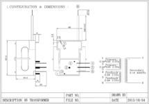
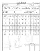
This circuit is built and we have been using it for a number of years, the 30-40 watts is a measured output not theoretical. Our power supply is max 10 amps at 15 volts so it is not possible to drive 35 amps through the primary. The transformer is also only capable of 100 watts, here are the specs on it.
--- Updated ---

It's difficult to make 3 windings interact properly right off the bat. Especially since you want an enormous step-up ratio (2000) and substantial power throughput.

In this development stage it's easer to start with a transformer with 2 windings, and create independent clocking signals to drive the transistors.

Then experiment with transformer parameters (particularly primary Henry value, step-up ratio), until you obtain your desired output voltage and power.

(Omit the capacitor across pins 1 & 3 at this point. It tends to cause LC resonance through the primary as though it were one winding. Instead I think you want current flow through each half of the primary winding at a time, at separate times.)

Observe voltage and current levels necessary to drive the transistors. When you get the system to perform as desired, you have an idea what is needed from the feedback coil. Write down values of bias resistors, voltage, bias current, xfmr primary Henry value, step-up ratio.

LTSpice is often favorably mentioned at this forum. The transformer options ought to cover 3 windings with or without center tap.

Add the feedback coil. Adjust its parameters so as to match signals driving the transistors.

At some point when you hook up transistor bias to the feedback coil, you still have to adjust everything so the system cooperates with itself. So it self-oscillates. You may need to add capacitors so you obtain the sine shape. Etc.
Brad thank you for the feedback, I follow what you are saying but I am not very versed in creating custom spice components. I just posted the specs for our transformer, do you think that it is possible to create a viable spice model that would simulate our circuit. I just don't want to spend time fumbling around if it doesn't seem feasible.
 

Attachments

  • Transformer Model (1).png
    Transformer Model (1).png
    383.5 KB · Views: 122
  • Transformer_GAP0.png
    Transformer_GAP0.png
    282.3 KB · Views: 127
Last edited:

Hi - please see the above, 20,000V x 0.02 amps out = 400W so perhaps you do not have 20kV or do not reach 20mA - or both ....
--- Updated ---

Also - straight away - I can see 4.5 T on the Tx spec sheet - this is a red flag for a transformer design - as you have 1/2 a turn of leakage inductance on each wdg - this leads to higher losses in the driving xtors ...!
--- Updated ---

Also the turns ratio as shown gives 10,667V from 12V in - so 20kV seems unlikely ...

--- Updated ---

100 watts out at 10 500V = 9.5mA - so not quite the 20kV & 20mA you stated above - always good to get the basics correct at the outset ...
--- Updated ---

also - to get a sine wave output - you need either a choke input Royer circuit - or a filter on the output of the royer - which is naturally a square wave out ...
Easy,

It is difficult to get current readings on the primary coil due to the fact that when the HV transformer comes on, our test equipment gets erratic and can get damaged (have lost a few meters already). We are inferring based off of what we can measure on the output. I measured 53ma pkpk on output, but not in phase with voltage. Less than 20ma rms? See attached, channel 3 is output voltage, channel 4 is current sense transformer with .1v/amp sensitivity. Input is based on 120v power meter that our DC power supply is plugged through, typical 5 amp peak and 2 amp avg but not completely accurate due to efficiency losses
TEK0027.JPG


Yes a choke input Royer or some variant of a Baxandall from what I am researching. The key is to keep the feedback coil influence on the frequency so we don't lose the dynamic frequency adjustment I described above.
 

What is the leakage of your extant tranformer/ - referred to the HV side ? also is that the complete ckt in post #1 ? - what is the load exactly ? - this will have a large influence ...

the scope shot shows 8kV rms, at 100 watts this is 12.5mA rms, which is approx 36mA pk-pk

on the pri side if your measurements are correct, ~ 3mV pk = 3A pk = 3 x 12V = 36W pk and less for average or rms power ... quite a bit of the current will be circulating between the capacitance of the HV wdg and its intrinsic inductance - it is a good thing to know what this self resonant frequency is ....!
 
Last edited:

Status
Not open for further replies.

Similar threads

Part and Inventory Search

Welcome to EDABoard.com

Sponsor

Back
Top