Continue to Site

Welcome to EDAboard.com

Welcome to our site! EDAboard.com is an international Electronics Discussion Forum focused on EDA software, circuits, schematics, books, theory, papers, asic, pld, 8051, DSP, Network, RF, Analog Design, PCB, Service Manuals... and a whole lot more! To participate you need to register. Registration is free. Click here to register now.

Simulation of a clapp oscillator in ADS

Havass

Newbie
Joined
Jul 18, 2023
Messages
2
Helped
0
Reputation
0
Reaction score
0
Trophy points
1
Activity points
17
Hello everyone,

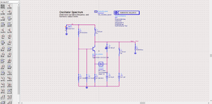
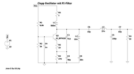
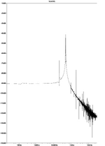
I want to design a clapp oscillator in ADS Keysight. I designed one and now I want to test it. I thought I could test it with Harmonic Simulation to test FFT. The oscillator should oscilate at 433 Mhz.
But the tutorial is so bad. And it doesnt. I hope one of you could help me.

p.s. I saw the other thread to this topic,but it still didnt work.

Best regards
 

Attachments

  • pastedImage.png
    pastedImage.png
    67.1 KB · Views: 94
You shouldn't blame ADS tutorial for non-functional oscillator dimensioning, I think. Particularly, there's no 433 MHz resonator. Dominant is L3/C9 series resonance at about 1.5 GHz, effectively shorted by C6/C7.
 
Hello,
it is not about the dimensioning. It is about simulating. I simulate it in LTspice and it was working. But I changed some values and also the design. But also with this design and this values it didnt work on ADS, because I am doing something wrong with HB-Simulation.
 

Attachments

  • BA.png
    BA.png
    42.6 KB · Views: 62
  • Plot BA.png
    Plot BA.png
    54.5 KB · Views: 67
We can't guess waht you tried. The present dimensions in post #1 definitely can't oscillate. I'm also not familiar with oscport probe, but the signal direction is wrong.
Point the arrow of the probe in the direction of positive gain around the loop
 
Your schematic can be called Clapp type because the resonant loop has a third capacitor inline with the inductor.
It's unconventional because it operates the transistor in common-base mode... whereas most Clapp (and Colpitts) configurations have the resonant loop connected to the bias terminal.

The transistor in common-base mode is turned On-and-Off by changing voltage on the emitter leg, thus changing the B-E relationship.

Running this simulation with common-base mode I find it takes extra time making adjustments until I find the right values to sustain oscillations.
I also find it cannot drive much of a load. Certainly not 50 ohms.

Clapp oscillator NPN common-base mode 276 kHz 5v supply.png
 
-Resonance Circuit resonates at 1.5GHz, not 433 MHz
-The Transistor has s-parameters only and it will not work with HB. Use nonlinear model.
-Collector is short circuited by 50 Ohm, wrong.
-Feedback elements ( caps) are probably wrongly dimesioned
-Oscillator port should be in inverted direction.
-Read and follow oscillator design handbooks and tutorials first then work.
 

LaTeX Commands Quick-Menu:

Similar threads

Part and Inventory Search

Welcome to EDABoard.com

Sponsor

Back
Top