Continue to Site

Welcome to EDAboard.com

Welcome to our site! EDAboard.com is an international Electronics Discussion Forum focused on EDA software, circuits, schematics, books, theory, papers, asic, pld, 8051, DSP, Network, RF, Analog Design, PCB, Service Manuals... and a whole lot more! To participate you need to register. Registration is free. Click here to register now.

[SOLVED] Full Bridge Inverter with MOSFET and IR2110 gate driver

Status
Not open for further replies.
You can use a driver like IR21834 which has programmable dead time that can be set by the hardware. Deadtime is adjustable from 0.4us to 5us.

how can one achieve this using pic micro

thanks
 

Put in a small period in the PWM generation where both outputs are off. Ensure that this time is maintained when one "switch" is turned off and the other one is turned on.
 

hi tahmid

is it the output of the FET driver or the micro?

thanks for ur help
 

If you want to do it in software using the PIC, then, you add deadtime in the code to affect the output signal from the microcontroller. If you want to do it in hardware, do so, using the driver.
 

If you want to do it in software using the PIC, then, you add deadtime in the code to affect the output signal from the microcontroller.

this is where i still have bit of confusion. is it when i am using the pic pwm in full bridge mode or how?

thanks
 

If you are using ECCP, then yes. If you are doing it in software, then add software delay. Whichever way you are using to generate the output signals, the deadtime must be incorporated into the software.
 

thanks tahmid
i guess i will stick to the ECCP mode. i guess its a easier to implement than writting the software for spwm.

thanks
 

problem solved thank~
 
Last edited:

I tried to simulate with along try it on the breadboard. And yesterday i succeeded to invert 7.4V DC voltage into AC.. Thanks for your help..

The ATmega8535 generating PWM, breadboard circuit of Full Bridge Inverter
59937d1312850931-1-breadboard.jpg


Output of the inverter, still in low switching frequency
59938d1312850948-2-inverted-low-frequency.jpg


Output of the inverter, trying high switching frequency up to 20kHz
59939d1312850964-3-inverted-high-frequency.jpg


now currently i designing my PCB with altium for this project. Btw, i read in the datasheet that 1N5818 reverse voltage rating is only 30V. I planned to use 36V DC voltage for my inverter. Do i need to change the diode? Is there other diode that have similar characteristic with 1N5818 but with higher reverse voltage rating?

About the proteus, do you have any fullbridge inverter simulation file that i can modified to simulate my circuit? it don't have to use IR2110, maybe with some optocouplers for the gate driver?


assalammualaikum.. can u share your proteus cct schematic
 

I made the attached circuit in a breadboard. Vdd of IR2110 and the PIC microcontroller is same +5v. It doesn't give output in the HO and LO pins but it becomes hot within several seconds. If +12v supply is removed, it is okay. The circuit is as almost same as shared by Tahmid. I used 1N5817 instead of 1N5818. What can I do to check whether it works. If it works I'll connect MOSFET gates in HO and LO pins.

IR2110.png
 

You might have previously damaged the IR2110. Without the MOSFETs connected, the IR2110 must not be getting this hot. Try the same with another IR2110.

Additional Comment: Connect 100nF capacitor in parallel with bulk capacitor (22uF - 100uF) between VDD and VSS and between VCC and COM.
 

You might have previously damaged the IR2110. Without the MOSFETs connected, the IR2110 must not be getting this hot. Try the same with another IR2110.

Okay. I'll change the chip. Could you please let me know using this circuit whether I can see the desired waveform at the HO and LO pint w.r.t ground? As I do not want to connect MOSFET for the initial test what about the pin Vs?


If the supply voltage is a stable dc (battery) do I need to connect your suggested capacitors? What is the advantage of connecting a small and a large capacitors in parallel across the supply voltage terminals?
 

Okay. I'll change the chip. Could you please let me know using this circuit whether I can see the desired waveform at the HO and LO pint w.r.t ground? As I do not want to connect MOSFET for the initial test what about the pin Vs?

You can observe output at LO. To observe output at HO, connect VS to ground. Then, observe output at HO. Then remove the connection from VS to ground.

If the supply voltage is a stable dc (battery) do I need to connect your suggested capacitors? What is the advantage of connecting a small and a large capacitors in parallel across the supply voltage terminals?

Yes, you need them. The supply voltage is a battery, but there will be voltage drops and maybe even spikes, especially in an inverter circuit. The large capacitor is used to provide current "surges" when required, eg during voltage drops. The small capacitor is for decoupling/bypassing.

Hope this helps.
Tahmid.
 

@Tahmid

Thanks a lot for the clarification...

You can observe output at LO. To observe output at HO, connect VS to ground. Then, observe output at HO. Then remove the connection from VS to ground.
I can also observe HO output by connecting oscilloscope probe with HO and Vs. So, I do not need to connect Vs to ground. Am I right?

Is there any full bridge high low side MOSFET driver chip available in Bangladesh to be used here instead of two IR2110 IC? It would be also helpful if I get some equivalent IC number available here.
 

I can also observe HO output by connecting oscilloscope probe with HO and Vs. So, I do not need to connect Vs to ground. Am I right?
No. I've tried that previously and it doesn't show output. You can try though.a

Is there any full bridge high low side MOSFET driver chip available in Bangladesh to be used here instead of two IR2110 IC? It would be also helpful if I get some equivalent IC number available here.

As far as I know, all you can get are IR2110, IR2112 and IR2113.

Hope this helps.
Tahmid.
 
As far as I know, all you can get are IR2110, IR2112 and IR2113.

These are same. Anyway, thanks a lot again...
So, full bridge is not available here in Bangladesh. :sad:
 

I found Logic-Input CMOS Quad Drivers (TC4467/TC4468/TC4469) in microchip site. Data sheet tells -
The TC4467/TC4468/TC4469 drivers can continuously
source up to 250 mA into ground referenced loads.
These devices are ideal for direct driving low current
motors or driving MOSFETs in a H-bridge configuration
for higher current motor drive (see Section 5.0 for
details). Having the logic gates onboard the driver can
help to reduce component count in many designs.

But it neither a level shifter nor a high low side driver. Can I use this IC here?
 

Take a look at Section 5.0 like it says (page 11 in the datasheet). It talks about H-bridge, where the high side MOSFETs are P-channel MOSFETs. So, you can't use it here.
 

Hi,
You have to use a fast switching diode at the bootstrap. So, switch to 1N5818 as the first diagram shows. Try with this circuit, I think this should work:
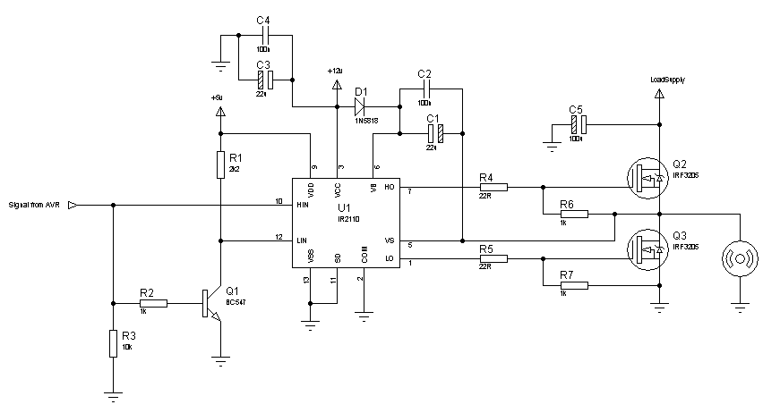
70_1312784222.png


Hope this helps.
Tahmid.

---------- Post added at 12:19 ---------- Previous post was at 12:17 ----------

C1, C3 - 22u
C2, C4 - 100n
C5 - 100u
R4, R5 - 22R
The rest of the resistors are in kilo-ohms.

Please can you tell me how you insert IR2110 in Proteus. I am using Proteus 7.6 but cant find this component in my Proteus library. Kindly tell me how I add this component into my library?

Regards
Imtisal
 

Status
Not open for further replies.

Similar threads

Part and Inventory Search

Welcome to EDABoard.com

Sponsor

Back
Top