Continue to Site

Welcome to EDAboard.com

Welcome to our site! EDAboard.com is an international Electronics Discussion Forum focused on EDA software, circuits, schematics, books, theory, papers, asic, pld, 8051, DSP, Network, RF, Analog Design, PCB, Service Manuals... and a whole lot more! To participate you need to register. Registration is free. Click here to register now.

[SOLVED] Full Bridge Inverter with MOSFET and IR2110 gate driver

Status
Not open for further replies.
The stored charge of the SF58 is much higher than the fast transistor IRG. As such , the conducting diodes do not switchOFF by the time the reverse diodes switch ON.As such there is a breakdown every time ...You can divert this by a small series inductance with the diodes ...OR a ferrite bead on the leads ..
The load does not drain the current as the voltage across this is not high enough .
You will need to try a switcher operating to 50KHz so that on load it drops down to 35KHz ...The PWM does not cater to this as the pulsewidth will narrow down the lack of load on the output stage.
 

Hello Tahmid,

I am in the process of designing a chopper to convert a Vdc to a alternating signal to passed through a step up transformer. I've read this string of post regarding the full bridge inverter and it has been quite informative and helpful. I am considering using the circuit you posted above (8-8-11) to get me started. Is your expertise still available if I have any questions down the road?

Thanks.
 

I will try to help as much as I can. Hope you can complete your design successfully. Just make sure you take care while designing the circuit as carelessness could prove lethal.
 

Dear, I read your post'sy I confused a little, I would serve adityo.kusumo circuit for controlling a motor of a wheelchair. I control speed and direction of this engine. The engine consumes about 5A unloaded and about 30A at full load. Thank you for your selfless help. I'm from Argentina. I'm using google translator.
 

Is that there are several circitos thread, but I wonder if that of adityo.kusumo
in response # 45 can be used as this. I'm using google translator.
That function would have a resistance between G and S. thanks for your answer Tahmid
 

Hi,
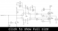
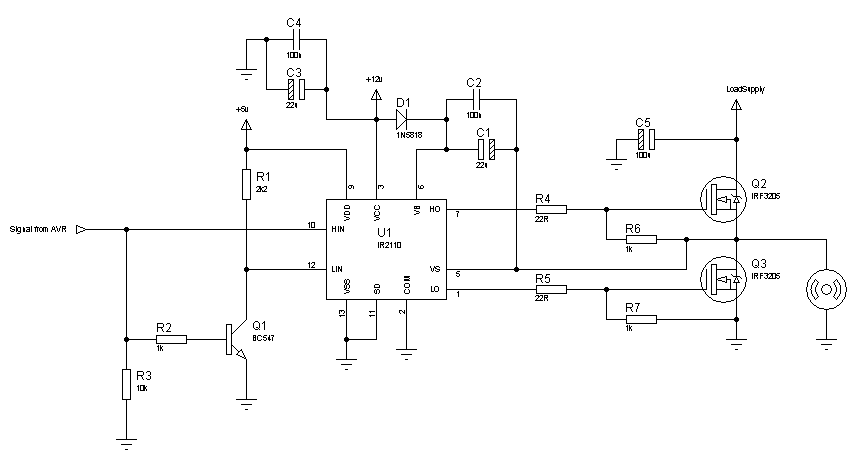
You have to use a fast switching diode at the bootstrap. So, switch to 1N5818 as the first diagram shows. Try with this circuit, I think this should work:
70_1312784222.png


Hope this helps.
Tahmid.

---------- Post added at 12:19 ---------- Previous post was at 12:17 ----------

C1, C3 - 22u
C2, C4 - 100n
C5 - 100u
R4, R5 - 22R
The rest of the resistors are in kilo-ohms.

hello Tahmid,
whether the series i can use to control motor dc 125Vdc, 3.5A 1/3Hp ?
so i just have to change IRF3205 with IRFP460?
 

Hello friends,

How do you make dead time in this circuits???

In the microcontroller? Or make it with hardware????

Thanks!

Basofias
 

You should make the deadtime in the microcontroller. IR2110 has only a very small internal deadtime.

Hope this helps.
Tahmid.
 

Hello Tahmid!

Ok! But, it's possible to make dead time with external hardware???

Thanks for the help!

Basofias
 

You can use a driver like IR21834 which has programmable dead time that can be set by the hardware. Deadtime is adjustable from 0.4us to 5us.

Hope this helps.
Tahmid.
 

Here what is the function of diode?
 

in first figure in this section you can see a diode 5818 thats accros mosfet , why do we use that?
 

The ckt operated beautifully with 400Hz input osc. switching .congrats ...

- - - Updated - - -

The ckt operated beautifully with 400Hz input osc. switching .congrats ...
 

hi friend can use this to his scheme to control a 24v motor, a wheelchair?
thank you
I'm from Brazil, I am wheelchair

- - - Updated - - -

hi friend can use this to his scheme to control a 24v motor, a wheelchair?
thank you
I'm from Brazil, I am wheelchair
Hi,
You have to use a fast switching diode at the bootstrap. So, switch to 1N5818 as the first diagram shows. Try with this circuit, I think this should work:
70_1312784222.png


Hope this helps.
Tahmid.

---------- Post added at 12:19 ---------- Previous post was at 12:17 ----------

C1, C3 - 22u
C2, C4 - 100n
C5 - 100u
R4, R5 - 22R
The rest of the resistors are in kilo-ohms.
 

Of course you can use it. But you have to make sure the drive signal is proper. And since this doesn't involve polarity switching, a simple 1-transistor driver may be simpler.
 
Of course you can use it. But you have to make sure the drive signal is proper. And since this doesn't involve polarity switching, a simple 1-transistor driver may be simpler.


I will do exactly what you suggested scheme
note: I'll do the full bridge to reverse the motor
the only doubt is whether I can connect the 24v load suplly?
and GND are connected together? is not necessary to separate any logical gnd?
I control everything with my arduino
the engine of my chair is 24v, maximum current is 20A
Sorry if I was not clear is what I use google translator

thank

Edson
 
Last edited:

MADE IN HALF BRIDGE DRIVER WITH AND IR2110 IRF3205 MOSFETS AND RAN everything right, NOW I WILL DO THE 2 SIDES OF THE BRIDGE AND SEE HOW IT WORKS
HUG TO ALL FRIENDS
EDSON
 

Status
Not open for further replies.

Similar threads

Part and Inventory Search

Welcome to EDABoard.com

Sponsor

Back
Top