Continue to Site

Welcome to EDAboard.com

Welcome to our site! EDAboard.com is an international Electronics Discussion Forum focused on EDA software, circuits, schematics, books, theory, papers, asic, pld, 8051, DSP, Network, RF, Analog Design, PCB, Service Manuals... and a whole lot more! To participate you need to register. Registration is free. Click here to register now.

Flyback converter in different operating modes

Patrick_66

Member level 3
Joined
Nov 18, 2023
Messages
60
Helped
0
Reputation
0
Reaction score
0
Trophy points
6
Activity points
406
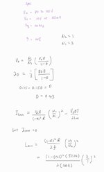
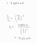
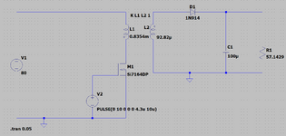
Based on the figures below, my parameters are Vin = 80 Vdc, Vout = 20 Vdc, Freq = 100 kHz, N1= 3, N2= 1. I have calculated the minimum inductance value which is around Lpri (min) = 0.8354 mH. Therefore, if I want to operate in DCM then I should set an inductance value less than Lpri (min) and if I want to operate in CCM then I should have a value higher than Lpri (min). The problem is I was able to operate in both DCM and CCM but the flyback converter failed to regulate the output voltage. I wanted to know what I had done wrong. Hope that someone can help me. Thank you.
 

Attachments

  • b.jpeg
    b.jpeg
    22.1 KB · Views: 64
  • a.jpeg
    a.jpeg
    13.9 KB · Views: 61
Hi,

is this a practical design, including a SMPS IC, or a theoretical concept only? If yes which one? Or how have you concluded "failed to regulate the output voltage"? What's about the required power?

BR
 
Hi,

is this a practical design, including a SMPS IC, or a theoretical concept only? If yes which one? Or how have you concluded "failed to regulate the output voltage"? What's about the required power?

BR

Hello Sir, as of now I want to learn the basics of the flyback converter first then only proceed to use the flyback converter in boundary conduction mode for constant current LED driver and I'm thinking of using IC like RT7306, RT7306, LT3799 to do the controlling of current and maintainning in BCM mode. If possible later on, can you teach me the equations required to build the whole system? For now the problem is when I use an inductance value lower than Lpri(min) then the Vout will not be 20V. For your info, my Vin is 80V and my proposed output is 20V and the output power is 7W with (20V and 350mA). I don't know maybe the equation that I use is wrong or my concept is wrong in the first place. Hoping that you might be able to enlighten me and sorry for my ignorance. Thank you in advance and have a nice day.
 

Attachments

  • d.png
    d.png
    30.3 KB · Views: 57
Hi,

if you decrease the primary inductance only, your output voltage should increase as your duty-cycle and input voltage is constant. By decreasing the primary inductance, you will increase the ratio N_secondary/N_primary.

Also, you do not have any control loop in your simplified example, so the voltage will change for sure. I would recommend, do not set your gate voltage rise and fall time equal to zero use e.g. 100ns. Further, the maximum drain-source voltage of the MOSFET you are using is only 60V.

BR
Hello Sir, if I decrease my Lpri while changing the Lsec based on the ratio values will the output voltage be regulated in DCM mode? If the output voltage is not regulated to 20 Vdc after I had decreased the Lpri and Lsec based on the ratio then how can I operate this system in DCM mode based on the specification that I'm currently using? Thank you for your advise.
 
Hi,

the term regulation means that the output is controlled to keep the output voltage close to its target voltage e.g. 20 V. Changing the transformer inductance does not reflect any kind of regulation, as this is a design parameter which will be constant in your actual circuitry. To regulate/control the output voltage, by means of keeping it as close as possible at e.g. 20V, you need a feedback loop which is providing somekind of information relative to the current output voltage. This can be realized by means of an optical device e.g. photo-mos or an auxilary transformer (winding) see [1]. This feedback information is usually used by some kind of SMPS IC to regulate the switching ferquency or the switching duty cycle.

[1] https://www.monolithicpower.com/en/how-to-design-a-flyback-converter-in-seven-steps

BR
 
Hello Sir, sorry for using the term 'regulate' in my previous conversation as I didn't have a feedback loop in my circuit. I was meant to ask whether I can get an output voltage of 20Vdc in DCM mode for my basic flyback circuit. Thank you sir for your reply.
 
Hi,


yes that's possible, keep in mind your primary inductance has to be below a certain value here <839.65µH. I performed the simulation for an inductance of 500µH. As you can see the flyback converter is operated in DCM. If the load stays constant, you can now adjust your output voltage by changing the swithicng frequency or duty cycle.

Flyback_DCM.png
 
When winding your own transformer it doesn't necessarily turn out exactly like the formulae. A few turns shy or overmuch, variance of coupling coefficient. You may need to give the primary a smaller Henry value in order to admit greater Amperes. It may be necessary to lengthen duty cycle. With a flyback it becomes hard to define a difference between DCM or BCM or CCM.

Tentatively a 4:1 ratio makes sense for stepping down 80V to 20V. My simulation illustrates waveforms that go with your specs. Generally the clock is 50% duty cycle.

In a flyback the flux builds during the first half of the cycle, then collapses during the other half through the secondary output. When experimenting I've found it helps to attach a full diode bridge at the secondary. This lets you check that current flows correctly in your system. Below, if D1 carries significant current, it's an error suggesting we're trying to get 'too much' from the transformer.

For simplicity I omit a snubbing network although it's good practice to include it.

Link to Falstad's website. Click to run my schematic on your computer in his animated interactive simulator:

tinyurl.com/2x7ouhku

Toggle Full Screen (under file menu).
Enlarge scope heights by dragging mouse upward from scope region.


flyback clk-driven 100kHz 80VDC to 20V 350mA (w slider adj).png
 
Last edited:
. Below, if D1 carries significant current, it's an error suggesting we're trying to get 'too much' from the transformer.

For simplicity I omit a snubbing network although it's good practice to include it.

Measuring D1 current looks like a good test for DCM mode, which depends on the decay time T=L/R being less than the off time.
This R would be the load referred to primary L including the effective resistance of a primary flyback clamp. Reducing L may be necessary to achieve this.
 

LaTeX Commands Quick-Menu:

Similar threads

Part and Inventory Search

Welcome to EDABoard.com

Sponsor

Back
Top