Continue to Site

Welcome to EDAboard.com

Welcome to our site! EDAboard.com is an international Electronics Discussion Forum focused on EDA software, circuits, schematics, books, theory, papers, asic, pld, 8051, DSP, Network, RF, Analog Design, PCB, Service Manuals... and a whole lot more! To participate you need to register. Registration is free. Click here to register now.

Forward vs Flyback for 125W

cupoftea

Advanced Member level 5
Joined
Jun 13, 2021
Messages
2,611
Helped
54
Reputation
108
Reaction score
115
Trophy points
63
Activity points
13,685
Hi,
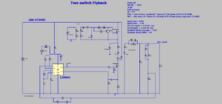
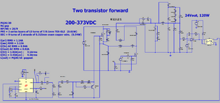
Do you agree the Two Transistor Forward ("2TFor") is preferable over the Two Transistor Flyback ("2TFly") for the following spec SMPS..
Vin = 200-373VDC
Vout = 24V
W(out) = 125W

The attached shows PNGs and LTspice's of the two converters for comparison.

The 2TFor is preferrable because ....
1...It does not need a gapped core transformer. (always difficult to find in stock)
(It does need a gapped output inductor core, but thats an easy part to do a multi-footprint
for, so that you dont suffer nil-stocks)
2...Less Secondary RMS current in the transformer.
3...Two output diodes, but thats good because they share the dissipation between them. Unlike
the flyback where one diode takes all the dissipation.
4....Less ripple requirement for output caps (4.5 times less).
5...If Vin suddenly falls below Vout* NP/NS then it wont blow up.
 

Attachments

  • 2 Switch Flyback.zip
    2.4 KB · Views: 45
  • Two switch flyback.png
    Two switch flyback.png
    64.4 KB · Views: 60
  • 2TF_LT1243_GDT.zip
    3 KB · Views: 45
  • Two Tran forward.png
    Two Tran forward.png
    88.3 KB · Views: 57
Hi, Sorry forgot to say that the 2TFor doesnt need a gap in the output inductor either, since it can use eg a sendust torroid.
Though the 2T Flyback wont actually blow up when Vin goes below vout x np/ns, it is not operable in that region.
 
Last edited:
Thanks, yes the Active clamp forward (ACF) can be a great choice.
Ayk, it allows pathways such that the magnetising current can be AC....sloshing back and forth without
staircasing...thus not saturating the transformer.
Though as the sim (LTspice) shows, the transformer leakage inductance means that you end up with a net
DC level in the magnetising current....which of course, we tolerate, but dont want. It means our margin
from saturation may be that little bit less.
Also, for offline use, it requires a high voltage PMOS, which of course, they are not always readily available,
and not always cheap. Ayk, it (reset) can alternatively be done with a hi side reset NFET, but that then needs a bootstrap hi side drive...and if you are putting
that in....then why not just use a two transistor forward, which has far more drivers available for it.

The ACF does give a bit of valley switching, always welcome, but perhaps not that brill when vin is low anyway.

All said and done...the biggest dissipation will often be in the output diodes...and so synchronous rectifiers will be the biggest friend...
...but synch rects can also be done with a "one transistor forward + reset coil", or with a "two transistor forward"..

And as ever, the ACF does nothing to reduce turn off switching losses. To reduce that we simply have to turn off the FET super-fast and put in a turn-off
snubber.

So you find yourself wondering if an ACF is really worth it. In these days, where our PSU's inevitably come from China, the semico's do not
produce too many ACF drivers....so if you do one, you always face the risk that the controller will go nil-stocked.

..Then we come scuttling back to the two transistor forward with synch rects. Or the one transistor forward with reset coil...and
synch rects.....or even, yes, the two transistor flyback. (+ synch rects).
 
Woops, forgot to attach the ACF LTspice sim
 

Attachments

  • ACF.zip
    1.8 KB · Views: 38
  • ACF.png
    ACF.png
    76.2 KB · Views: 31
the transformer leakage inductance means that you end up with a net
DC level in the magnetising current....which of course, we tolerate, but dont want. It means our margin
from saturation may be that little bit less.
Not really true at all, the mag current goes up and down - just like any forward or flyback.

it requires a high voltage PMOS
Ah - no, most are made with 2 x N fets.

The ACF does give a bit of valley switching
It can, for the simple resonant reset shown below, the fet must pick up the reflected current flowing in the output choke, the volts will be Vin at turn on.

the ACF does nothing to reduce turn off switching losses
actually the turn off voltage, at turn off is the clamp voltage, often just 30% higher than Vin, then curving over to about 160 % of Vin peak in a nice arching curve - instead of flying up to 2 x Vin at the instant of turn off - so some what easier - and much less RFI - shown in a simple resonant reset converter here:

1708388327886.jpeg

operating at full power, Vds - blue, I_fet, the other
--- Updated ---

and with larger resonant reset clamp cap:
1708388513317.jpeg

colours reversed from above - note the turn off Vds is not a fast jump up, but a 300nS curve to initial Vpk.
--- Updated ---

A single ended resonant reset forward is good for 250W easily.
The ACF can go faster and have lower turn on losses
 
Last edited:

LaTeX Commands Quick-Menu:

Similar threads

Part and Inventory Search

Welcome to EDABoard.com

Sponsor

Back
Top