Patrick_66
Member level 3
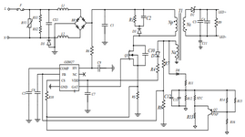
Hello everyone, wanted to ask how to obtain all the capacitance and resistance values in this paper as the datasheet for the IC did not mention how to get it as well as the paper. Hope that someone can help with that.
Follow along with the video below to see how to install our site as a web app on your home screen.
Note: This feature may not be available in some browsers.
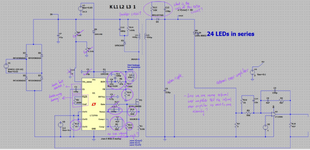
Hello Sir, the datasheet did not mention the capacitance and resistance value for the circled part (purple) based on the figure below. May I ask how to find all of those values? Thank you for your time.
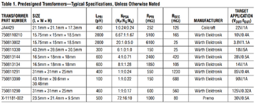
Hello Sir, if I want my Vout to be 85 Vdc and Iout 0.4A which is the same as the specification given by the predefined transformer model 750811291. How do I know the range of value to adopt based on my defined Vout and Iout? Thank you Sir for your time.The schematic consists of several sections. Each has its function in the overall system.
Once you choose your desired voltage and current levels, those various sections tend to adopt a range of values that go with those voltage and current levels. This is done with both the power supply (input) and the supply (output) to the final load.
 . This is because I compared the circuit diagram shown in the datasheet for LT3799 and the parts that are circled in purple show different values when compared with 20W, 4W and 14W LED but the datasheet did not mention the equation to obtain the values for the circle part so I was confused how to get the values. Once again thank for sir for your patience towards me and willingness to teach a person like me.
Vout to be 85 Vdc and Iout 0.4A which is the same as the specification given by the predefined transformer model 750811291. How do I know the range of value to adopt based on my defined Vout and Iout?