Continue to Site

Welcome to EDAboard.com

Welcome to our site! EDAboard.com is an international Electronics Discussion Forum focused on EDA software, circuits, schematics, books, theory, papers, asic, pld, 8051, DSP, Network, RF, Analog Design, PCB, Service Manuals... and a whole lot more! To participate you need to register. Registration is free. Click here to register now.

fixed bias circuit (amplifier working in frequency range 20 hz-20 khz)

Status
Not open for further replies.

mohangupta84

Newbie level 5
Joined
Jun 6, 2012
Messages
10
Helped
0
Reputation
0
Reaction score
0
Trophy points
1,281
Activity points
1,384
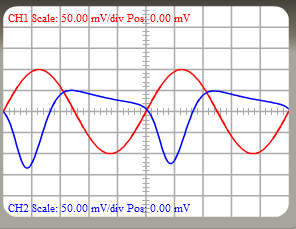
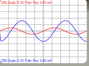
i am not getting output in frequency domain..
component values are
R7=100 OHM C0=148.2 MICROFARAD
R1=240 KILOOHM R4=2.2 KILOOHM
R6=1.6 KILOHM R10=681 OHM
C4=646.78 MICROFARAD

Can you suggest me the way ,,input and outpur waveform in time domain are not in phase..
5_1339064103.png


It's the phase shift introduced by the input and output capacitors. Try it at higher frequency and you should see the amount of phase shift change. Remember that the current leads the voltage when charging or discharging a capacitor.

Brian.
 

will you suggest me the basic steps for design so that i could get right output both in frequency as well as in time domain..i think i am doing some mistake in calculation..
 

Did you check the DC operating point first? I think the transistor is saturated. You can fix that one of three ways:
  • Make R1 much bigger e.g. 1M or 2.2M.
  • Connect the top of R1 to the collector of the transistor instead of the power supply.
  • Add another resistor e.g. 47K from the base of the transistor to ground.
 

what is the purpose of connecting resistor of 47 k between base and ground...

- - - Updated - - -

52_1339068183.png


- - - Updated - - -

52_1339068183.png


- - - Updated - - -

whwn i connected 47 k resistor between base and ground ,output is as shown ,,,.
52_1339068183.png
 

I thought the supply voltage is 27V again. Is it not?
 

what is the purpose of connecting resistor of 47 k between base and ground...

Mohan, if you really knows nothing about the purpose of such a resistor, I propose to follow my suggestion:

Instead of trying to find a workable transistor amplifier based on a trial-and-error procedure you really should study some transistor basics, in particular what a suitable operating (bias) point is and how it can be realized.
I am afraid, otherwise your activities are a waste of time.

LvW
 
  • Like
Reactions: FvM

    FvM

    Points: 2
    Helpful Answer Positive Rating
In addition, it's obvious that your original circuit had been biased correctly, at least for the AC voltage signal in your experiment. The 47k resistor made bias worse. By the way, without knowing the supply voltage, noone can calculate the optimal bias.

will you suggest me the basic steps for design so that i could get right output both in frequency as well as in time domain..i think i am doing some mistake in calculation..
You didn't tell a specification of "right output" or what you calculated at all.

It's not so obvious, because the ideal amplifier (with larger capacitors) will show an inverted rather than "in phase" output signal. Referring to transistor amplifier basics is also suggested in this regard.
 

right boutput means i want frequency response between 20 hz-2o khz and a perfect gain in time domain......

- - - Updated - - -

i want to desifn an amlifier which amplifies audio signal between 20 hz -20 khz
 

Putting aside meaningless slogans like "perfect gain", you need to specify a maximum accepted phase error. Then calculate the high-pass corner frequencies respectively.

The purpose of a constant phase for regular audio applications can be doubted. It may have a meaning for "high end" audio, but unlikely for an amplifier mostly lacking linearity.
 

Status
Not open for further replies.

Similar threads

Part and Inventory Search

Welcome to EDABoard.com

Sponsor

Back
Top