Continue to Site

Welcome to EDAboard.com

Welcome to our site! EDAboard.com is an international Electronics Discussion Forum focused on EDA software, circuits, schematics, books, theory, papers, asic, pld, 8051, DSP, Network, RF, Analog Design, PCB, Service Manuals... and a whole lot more! To participate you need to register. Registration is free. Click here to register now.

Fast step signal generator.

Status
Not open for further replies.
I cant find fast enought one. And to be capable to drive 100mA.
 

Today I look more on digital switches. But seems that is not good for my application. As I need fast rise time the switch should have one input tied to VCC and output controlled with control input. And that is not situation for what the switch is designed.
For example ADG902 can work up to 4.5 GHz. That should be nice. But TurnOn time is just 3.1 nS up to 5.5 nS. So fast operation switch doesn't need to have fast turn on time. If someone know for (available) digital switch with turn-on time under 1nS to be powered with 5V (3.3V is little limiting for that operation) and capable to deliver at least 100mA you are welcome.
 

Your current specification may require paralle connection of multiple switches.

The other point is that ton/toff numbers are usually propagation delay rather than rise time numbers. Need to read the datasheet fine print and parameter measurement setup.
 

I do read datasheet. And can't find the switch with Ton or rise time to be under 1nS. I assume when switch is closed the signal can travel fast from source to drain. But when switch is in transition from off to on the gates must be charged and this take more time than signal propagation from source to drain.
Paralelling gates can work but if they have different delay (skew) the signal is not clean.
 

Hi,

someone know for (available) digital switch with turn-on time under 1nS to be powered with 5V

I´d say my recommendation of post#7 is close...


Klaus
 

Well TS5A23160 data sheet says:
1.65 to 5.5V supply - Fine for me
On state resistance 0.9 Ohm - Perfect for me
Bandwidth 100MHz - Probably to low.

TurnOn/TurnOff 2.5nS/6nS -That's BAD. (Based on figure 18 that's really propagation delay)
I can't find real slew rate. But based on frequency response it isn't under 1nS.
 

Hi,

Bandwidth 100MHz - Probably to low.
Test circuit is with 50 Ohm signal generator impedance. But in your case it is very low input impedance.
Therefore i expect better results.

TurnOn/TurnOff 2.5nS/6nS -That's BAD.
You don´t care about delay, you are focussed on rise time.
It is specified with a signal level of 90% but with logic circuits it is measured at 50%.

Now assume only the RC curve. It needs about 0.7 tau to be at 50%, but it needs 2.3 tau to be at 90%.
This means if the datasheet for both ICs say the same rise time, then the switch is more than 3 times faster than the logic IC.

For sure the reality is somewhere inbetween 1 and 3, but maybe worth a try.

Klaus
 

I got little under 2nS with 74LVC4066 and little better with74LVC14. But I have 5 gates paralleled in LVC14 and 4 switches in LVC4066. All drive 50 Ohm resistor. If Drive 5m of twisted pair the LVC14 is the clean winner. Seems that capacitance of twisted pair affect more 4066 than LVC14. Need to find some stronger driver. Thus I tried simple Pfet BS208 and got 2.5nS step practically same if drive 50Ohm resistor or twisted pair. Need to got some faster Pfet with as small as possible gate capacitance and low voltage treshold to be able to switch with AVR.
 

I got little under 2nS with 74LVC4066 and little better with74LVC14.
According to known device data, this doesn't sound like 74LVC speed is the bottleneck. Should easily achieve < 1ns tr/tf with 4 - 5V supply. Similar thing as the previously report ringing. I presume, the results have more to do with your layout and used measurement tools.

My reference is a 1 GHz oscilloscope with active or resistive GHz probes respectively all 50 ohm connection.
 

I have only 250MHz osciloscope. So I can't measure slew rate with it. But I do see ringing of AC14 clearly. So All data I got is from ADC in TDR alone. And maybe I have trouble here. I capture signal with track and hold circuit based with LVC4066 charging capacitor and after that there is buffer opamp (slow) and ATTINY with own ADC (even slower) So Idea is to track and hold value, then do little wait to opamp setle and got stable voltage on AVR pin and then to trigger adc. Maybe I need to improve track & hold circuit as maybe there is slew rate limited too.. Need to found someone with faster oscilloscope to check if my generator is bad or T&H circuit. But as I look curve on AC14 the step response is great and probably T&H works well.
 

...

I do found MCP1407 driver and tested. Result was clean step with (slow) risetime of 13nS. Unusable for that application. I do check response with 1nF capacitor connected and risetime barely change. So 74AC14 is winner with 2.1nS and bad ringing, and HC14 or BS170 as inverter second with 3.3nS without ringing. So how to go under 1nS? Inverter with discrete components?
No doubt your measurement methods leave much to be desired.

This must be done with pure 50 Ohm matched source, cable and termination.
Not any coax will do, nor will your 10:1 probe.

Add impedance matching series divider to semi-rigid or coax or microwave suited coax to 50 Ohm term in scope for proper signal capture.

Remember what I wrote about source impedance vs logic family and supply voltage.
2013-12-11 17.06.49.jpg
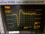
This event although, not from logic, was an AC coupled transient measured 10m away with a current transformer, good coax and internal 50 Ohm term. Actual rise time is much faster but limited by speed of 300MHz scope < 1ns. Since the CT is AC coupled, the area under the curve of the return to zero "overshoot" is equal to the pulse area, indicating AC response not DC response.

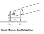
The next best method is shown below but will be limited by the quality and bandwidth of the probe and scope.
proper scope measure.jpg
 
Last edited:

Status
Not open for further replies.

Part and Inventory Search

Welcome to EDABoard.com

Sponsor

Back
Top