Continue to Site

Welcome to EDAboard.com

Welcome to our site! EDAboard.com is an international Electronics Discussion Forum focused on EDA software, circuits, schematics, books, theory, papers, asic, pld, 8051, DSP, Network, RF, Analog Design, PCB, Service Manuals... and a whole lot more! To participate you need to register. Registration is free. Click here to register now.

equivalent circuit model for dual and triple band antenna?

Status
Not open for further replies.

shazdek0ch0l0

Member level 3
Joined
Jan 2, 2009
Messages
63
Helped
1
Reputation
2
Reaction score
1
Trophy points
1,288
Activity points
1,654
equivalent circuit model for dual or triple band antenna?

Dear,
are you have any ideas about 2band or 3band (or mult-iband) antenna equivalent circuit?
(in transmission line or lumped element)

Is there any source or book about this subject?
 
Last edited:

Dear,
are you have any ideas about 2band or 3band (or mult-iband) antenna equivalent circuit?
(in transmission line or lumped element)

Is there any source or book about this subject?
I don't know any references on this, but here's a quick few thoughts that I have.

1) Knowing the S-parameters at a specific frequency, it would be possible to convert that to a series R and an L or C. For a half-wave dipole it would be a resistor of about 73 Ohms, in series with an inductance presenting an inductive reactance of 42 Ohms. It would be easy to convert that 42 Ohms into an inductor value in Henrys.
2) The above would tell you nothing about the loss resistance of the antenna. So if the S-parameters indicate an impedance of 30-j 100, you have no idea what fraction of that 30 Ohms is the radiation resistance and what is the loss resistance.
3) An equivalent circuit would tell you nothing about the radiation pattern. So two antennas could have the same equivalent circuit, but have a different radiation patthern.

I don't know if in general its possible to find an equivalent circuit that presents the same S-parameters as your antenna at more than one frequency. Clearly for a single frequency you only need two components, but for two frequencies you might need 3, 10 or 1000, I have no idea. It might be impossible to do.

As a matter of interest, what are you trying to achieve with your equivalent circuit? Do you want it to provide just the same S-parameters, or do you want to quantiry the loss and radiation resistance separately?
 

thank you
i only want an equivalent circuit with the same S-parameter of the main antenna
 

thank you
i only want an equivalent circuit with the same S-parameter of the main antenna
The subject says "dual and triple band antenna". Do you want it to have the same S-parameters at 2 frequencies (for a dual band antenna), or do you want it to have the same S-parameters across the whole band, which is an infinite number of different frequencies?

Does it have to be exact, or is approximatley the same S-parameters OK?

Is it an academic exercise, where you are probably looking for an exact solution, or one of practical interst where you probably only want the circuit to have approximately the correct S-parameters?

I'm thinking if there are N frequencies you want this S-parameters the same as your antenna, then there must be 2*N impedances that must be right, since an S-parameter gives you both the real and imaginary parts. I'm sort of guessing here, but I'm thinking

1) To match the S-parameters exactly for N frequencies you will need at least N resistors and N reactances in a network.
2) For small values of N, analysical solutions should be possible, but for large N, only numerical ones probably exist.
3) It looks like an issue of solving 2*N simultaneous equations to solve for N different frequencies.

Note I'm not saying 1, 2 or 3 are correct - only some vague thoughts I have on the matter.

There's probably some basic theory one learns in a first year degree which will tell you whether this is possible or not. I've forgotten any such theory if I was ever told one.

It's an intersting question you pose.
 
Last edited:

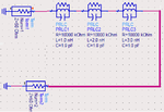
i was drawn the below circuit on ADS for triple resonant frequency, but i dont know it is true or not, because it has triple resonances but in S21 not S11
Untitled.png
 
Last edited:

i was drawn the below circuit on ADS for triple resonant frequency, but i dont know it is true or not, because it has triple resonances but in S21 not S11
An antenna is resonate when it's input impedance is real. An antenna does not have an output port - it's designed to radiate the signal. So drawing a two port object and having S21 being real is nothing to do with resonance.

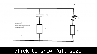
If you work out the resonate frequency of the attached drawing,


which is a parallel tuned circuit, you get a surprising result if you set R=sqrt(L/C). The parallel tuned circuit is resontate at all frequencies! I leave you to prove that if you want. Sorry the circuit looks a bit poor, (especially the inductor), but I don't have any software on this laptop for drawing components, so just used Windows Paint. But you should get the picture.

Why do you want an equivalent circuit of an antenna which is resonate at 2 or 3 frequencies? Would a simple resistor not be good enough - that has a real input impedance at all frequencies, so will be real at the 2 or 3 resonate frequencies of your antenna.

Deborah
 
you are right, i should not simulate antenna between two port, I will try again, thanks
 

I have an idea, port21 acts as one port in rotation of the structure like below:
do you think it is true?

345.png
 

so because of that, S21 has 3ple resonance!


but still i dont have any idea about S11
 

Delete port 2 and replace it with a resistor (50 ohm?)
 

now i delete port2 and replace with 50ohm and the result is same as S11 in previous structure.
 

What is the purpose of this equivalent circuit?
 

Thinking about this more, for a 3-band antenna, you have 9 known parameters - three frequencies, the 3 real parts of the impedance at these frequencies, and the 3 imaginary parts at the three frequencies. (The impredances are trivially derrived from the S parameters).

So I think you might need 9 elements in your network, not 6 as I first thought.

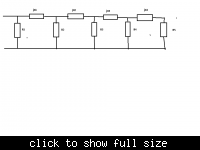
So how about this network:


That has 9 components of unknown values - 5 resistors and 4 reactive components.

You have 9 knowns, so there's a set of 9 simultaneous equations to be solved to find the values of R1, R2, R3, R4, R5, X1, X2, X3 and X4. So find the input impedance of that network in an analystical form, which should be fairly easy, then set up 9 simultanous equations. Using a program like Mathematica, you can probably solve this all analytically. If not, it should be possible to solve it numerically.

Just a thought - I have no proof this will work.

It is first year electronics degree stuff to derrive the input impedance of that network, but I did the first year of my degree a very long time ago!


Deborah
 

Have a look at this paper if you have access to IEEEXPLORE.

Sobhy, M.I.; Sanz-Izquierdo, B.; Batchelor, J.C.; , "System and Circuit Models for Microwave Antennas," Microwave Theory and Techniques, IEEE Transactions on , vol.55, no.4, pp.729-735, April 2007
 

What is the purpose of this equivalent circuit?

Dear Debora
thanks for useful comments.
suppose I have an antenna and I want to know
1.how dose this antenna radiate?
2.how is the E-field distribution or current density of the radiator?
3.what's the antenna resonate frequency?

Are these purpose sufficient to knowing the equivalent circuit of an antenna?

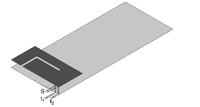
more exactly suppose I have this patch antenna (attached image)


for this antenna what's the equivalent circuit?
And in addition of above reason what's the importance of an equivalent circuit of an antenna of your view?
I'm really appreciate you if you explain more.
thanks
 

Dear Debora
thanks for useful comments.
suppose I have an antenna and I want to know
1.how dose this antenna radiate?
2.how is the E-field distribution or current density of the radiator?
3.what's the antenna resonate frequency?

Are these purpose sufficient to knowing the equivalent circuit of an antenna?

An equivalent circuit, made from "transmission line or lumped element" (as you requested in your very first post), can't possibly represent anything about the radiation pattern, E-field distribution, or current density of the antenna.

It would however be possible to make an "equivalent circuit", which was equivalent in the sense of having the same resonate frequency.

And in addition of above reason what's the importance of an equivalent circuit of an antenna of your view?
I'm really appreciate you if you explain more.
thanks

To be honest, I don't much find equivalent circuits that useful. They are used in text books to show an antenna has loss resistance and radiation resistance, as well as a reactive component of input impedance, but one does not find many "equivalent circuits" in any antenna book.

In a systems level diagram, it might be worthwhile to represent the antenna gains and path loss as just a simple attenuator. Knowing the noise figure of the receiver, one could compute the transmit power necessary for a given S/N ratio. But I have personally not found much use for equivalent circuits, as they tell you nothing about the important characteristics of the antenna such as its gain or radiation pattern.

The equivalent circuit for your antenna at one frequency would consist of three components in series:

* R_rad, the radiation resistance
* R_loss, the loss resistance
* X, the reactance, which will be capacitive or inductive depending on the antenna.

The efficiency of your antenna, which would range from 0 (perfect dummy load) to 1 (perfect antenna), would be:

R_rad/(R_rad + R_loss)

You need to appreciate that circuit level simulations using R's, C's, IC's and transistors are only useful when the circuit elements are sufficiently small that radiation effects can be ignored. Once components get sufficiently large that they radiate, circuit level simulators are of very limited use.

To know the important characteristics of your antenna (its gain, its radiation pattern, input impedance) etc, then you basically have two choices.

1) Measure them.
2) Simulate them using a full 3D EM simulator.

I think you are possibly asking the wrong questions. Tell people what you actually want to achieve - not how you think you might achieve it.

Deborah
 

Dear Deborah
Thanks for your complete and useful comments
I found in fact something in the antenna designing that by controlling the near field characterize I can tune the far field distribution.
one of the near field feature is the Input impedance .when it is high the antenna radiate well.
for example I calculate the input impedance of an antenna by Smith Chart and it was equal Z(in)=78-j16 in the resonate frequency.
so I need the equivalent circuit to show me the input impedance of the antenna in a frequency band of 300-600 MHz.and show me it is maximum at the resonate frequency.I know in 402MHz my antenna has the large value of the input impedance and it radiate well.
do you believe that here the equivalent circuit is useless too?
 

Dear Deborah
Thanks for your complete and useful comments
I found in fact something in the antenna designing that by controlling the near field characterize I can tune the far field distribution.

The far field can be computed from the near field via a Fourier Transform.

one of the near field feature is the Input impedance .when it is high the antenna radiate well.
for example I calculate the input impedance of an antenna by Smith Chart and it was equal Z(in)=78-j16 in the resonate frequency.
That's wrong. The antenna can not be resonate if the input impedance is 78 - j 16. By definition of resonance, it occurs when the input impedance is purely resistive. For example, 45 + j0, 1000 +j 0 and 0.1 + j0 are all resonate, but 78 -j 16 Ohms is not resonate.

I'm don't think it's true to say "one of the near field feature is the Input impedance", though that might be a case of different people using different terminology. But certainly if you try to plot the near field of an antenna with a program like HFSS, it does not give you the input Z.

so I need the equivalent circuit to show me the input impedance of the antenna in a frequency band of 300-600 MHz.and show me it is maximum at the resonate frequency.I know in 402MHz my antenna has the large value of the input impedance and it radiate well.
It's a big generalization to say when the input impedance is high, the antenna radiates well. In fact, I know of several designs for antennas which have high directivity, and so would have high gain is the losses were low. But their input impedance is impractically low, making it difficult/impossible to feed them.

do you believe that here the equivalent circuit is useless too?

I think you need to sit and read some basic antenna books, and get a good grasp of the definitions of different parameters for antennas before you worry too much about equivalent circuits for dual and triple band antennas. I personally think you are worrying too much about an equivalent circuit, and should be concentrating on other aspects of the antenna instead.

You would be far better understanding single frequency antennas properly before worrying about dual and triple band antennas.

I think you post has been most interesting in some of the questions you have asked. I'd never even considered an equivalent circuit for antennas in the way you are. But I'm not sure such circuits will be much use to you.

When you come to matching an antenna, you will certainly need to know the S parameters, but you don't need to work out component values for any equivalent circuit. If you think about it, for a single frequency there must be an infinite number of circuits which will present the same impedance. Let's assume the simplest case, and assume a resonate antenna with an input impedance of 50 Ohms. There are many equivalent circuits

1) Single 50 Ohm resistor
2) Two 100 Ohms resistors in parallel
3) Three 150 Ohm resistors in parallel
4) A 40 Ohm and a 10 Ohm resistor in series
5) A 50 Ohm resistor, in series with a capacitor with a reactance of -j 100 Ohms and an inductor with a reactance of + j 100 Ohms.

So for a single frequency, there are an infinite number of circuits having the same input impedance. So what use are they really?


Deborah

---------- Post added at 01:50 ---------- Previous post was at 01:23 ----------

Dear Deborah
Thanks for your complete and useful comments
I found in fact something in the antenna designing that by controlling the near field characterize I can tune the far field distribution.

The far field can be computed from the near field via a Fourier Transform.

one of the near field feature is the Input impedance .when it is high the antenna radiate well.
for example I calculate the input impedance of an antenna by Smith Chart and it was equal Z(in)=78-j16 in the resonate frequency.
That's wrong. The antenna can not be resonate if the input impedance is 78 - j 16. By definition of resonance, it occurs when the input impedance is purely resistive. For example, 45 + j0, 1000 +j 0 and 0.1 + j0 are all resonate, but 78 -j 16 Ohms is not resonate.

I'm don't think it's true to say "one of the near field feature is the Input impedance", though that might be a case of different people using different terminology. But certainly if you try to plot the near field of an antenna with a program like HFSS, it does not give you the input Z.

so I need the equivalent circuit to show me the input impedance of the antenna in a frequency band of 300-600 MHz.and show me it is maximum at the resonate frequency.I know in 402MHz my antenna has the large value of the input impedance and it radiate well.
It's a big generalization to say when the input impedance is high, the antenna radiates well. In fact, I know of several designs for antennas which have high directivity, and so would have high gain is the losses were low. But their input impedance is impractically low, making it difficult/impossible to feed them.

do you believe that here the equivalent circuit is useless too?

I think you need to sit and read some basic antenna books, and get a good grasp of the definitions of different parameters for antennas before you worry too much about equivalent circuits for dual and triple band antennas. I personally think you are worrying too much about an equivalent circuit, and should be concentrating on other aspects of the antenna instead.

You would be far better understanding single frequency antennas properly before worrying about dual and triple band antennas.

I think you post has been most interesting in some of the questions you have asked. I'd never even considered an equivalent circuit for antennas in the way you are. But I'm not sure such circuits will be much use to you.

When you come to matching an antenna, you will certainly need to know the S parameters, but you don't need to relate them to any equivalent circuit.
 
Dear Deborah
I greatly appreciate you for your patience in answering the whole of my questions.
I feel ashamed if I want to ask any further questions ;-)
but I think you forgive me because of my inquisitive and unremitting in understanding.
I simulated an antenna and find the S11 like the following image and it's obvious from S11 that this antenna resonate at 399MHz. from the smith chart I can find that the input impedance is equal Z=67.48-j9.8
I know that at the resonating frequency the Image component of the input impedance is zero but the smith chart show me another result 8-O
So May it not be the input impedance?
Z_real.JPG
Z_image.JPG
 
Last edited:

Status
Not open for further replies.

Part and Inventory Search

Welcome to EDABoard.com

Sponsor

Back
Top