Continue to Site

Welcome to EDAboard.com

Welcome to our site! EDAboard.com is an international Electronics Discussion Forum focused on EDA software, circuits, schematics, books, theory, papers, asic, pld, 8051, DSP, Network, RF, Analog Design, PCB, Service Manuals... and a whole lot more! To participate you need to register. Registration is free. Click here to register now.

Electromagnetic interference on PIC16F877A?

Status
Not open for further replies.

umery2k75

Advanced Member level 1
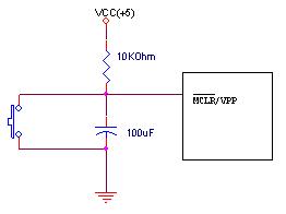
Joined
Apr 19, 2006
Messages
434
Helped
41
Reputation
80
Reaction score
15
Trophy points
1,298
Location
Pakistan
Activity points
5,748
pic16f877a reset

I have compiled a simple program of serial communication on CCS compiler.This sends the data on the serial port.I'm using Hyper Terminal for monitoring the data sent by PIC.Now I don't have consistency of getting same result every time.I have not yet made it's power supply, so I am giving it by laboratory bread board.

1)Either I get no output from PIC.
2)Either my program on the PIC erases up automatically.I then have to reprogram my PIC again with IC programmer.
3)On bringing my finger closer to the PIC controller(I don't even touch my finger), it get reset and display letter 'A' on all over the screen.
4)Some times I have touched the PIC IC and the results were the same.

Code:
#include<16f877A.h>
#use delay (clock=20000000)
#fuses NODEBUG,HS,NOWDT,PUT,NOPROTECT

#use rs232(baud=9600,xmit=PIN_C6,rcv=PIN_C7)
main()
{
   int i;

   while(1) {
            i=65;
            do
               {
               putc(i);
               delay_ms(1000);
               i++;
               }
             while(i<=122);
            }
}

Here's the video


Please tell me as how can I remove this problem and why such thing happen?
 

pic16f877a entering lvp mode

Hi!
Have u pulled up the reset pin (PIN No.1) of the controller through a suitable resistor (e.g. 1K)?
Also use decoupling capacitors (100nF) on the power supply pins of the controller.
Regards.
 

pic16f877a enters lvp mode

Put 100uF capacitors close to every power supply pins. From VDD to VSS.
Sorry i cannot see the video because of a firewall.
Did you connected a MAX232 or another driver??? Did the TX line on the PIC is connected to the RX line on the PC?? Once when I connected TX to TX had a similar problem, it only sent character 'A' and another wierd characters and constantly resetted.
 

reset circuit pic16f877

Check the power voltage, is it ok with MCU and other IC?
A good power is important. If you have unstable power supply,
you are facing many unpredicatable problem.


Worst case, make your own PCB board for the testing.

I don't think it is "Electromagnetic interference" or MCU problem.
 

electromagnetic interference with pics

I'm using the MAX232 IC.There are no logical errors in the circuit.This circuit has operated accordingly as it was supposed to, but I think that upon bringing the finger close to IC.It made it reset and the character 'A' starts appearing, as 'A' must appear on every start of program.I have a very stable power supply.

I haven't use the decoupling capacitor.I made the (MCLR bar) pull up by adding the 10Kohm resistor, but I haven't use the capacitor, maybe due to a little fluctuation in voltage +5V drops to 0V, but on the other end,I also think it's not that easy to shift from 5 to 0V with ease.I haven't notice anything of this type when I had used the 89C51.These are the two RESET circuitry, for 89C51(I didn't encounter any problem) and PIC16F877A(in which I'm having problem).


good supply to use for pic16f877a

Please use Terraterm Pro.

Hyperterminal is buggy.. a lot !
 

pic16f877 lvp disable

did decoupling caps solve the problem ?
 

pic16f877a diode reset line

No, I didn't get success even after I added the decoupling capacitors.I add 100uF on the incoming +5V and Gnd


then I add 0.1uF capacitor on the VDD & VSS(Pin 11,12)


then I add another 0.1uF capacitor on the VDD & VSS(Pin 32,31)


then I add another 100uF capacitor on the Reset Pin of controller


The reset circuit looks like this

95_1200632863.jpg
 

working of pic16f877 reset circuit

Are all Vdd voltages within 300mV of eachother? Do you see any ground bouncing? A good practice to make circuits is this: connect all groungs at microcontorller and then route a master ground to the power inlet of your circuit. Do the same for Vdd. Do not be fooled by small currents in the datasheet. Spikes generated by fast logic are huge, the bigges ones come from your oscillator circuit. Thick wires help, I use Φ=0.5mm .

Are you absolutely sure you have a good power supply?

Did you disable all peripherals not needed? Interrupts? Is your oscillator stable?

What is the deal with the socket?

Interference is possible and was observed on several MCUs, I personally experienced some on 877A and 684A. The thing affected was the ADC, but never the execution of the program in the MCU.

Something is seriously wrong if your MCU gets blanked.

Is the RS232 transciever wired correctly? Inputs of the MCU should never see a voltage exceeding the supply voltage or swing lower than the MCU ground.

Bypass the MCU supply right at the supply pins.
 

electromagnetic

Reset doesn't really need any capacitor, a simple 10K pullup is all you need. What does your power supply look like?
 

serial communication with pic 16f877a

Yes, reset doesn't need capacitor.I am using laboratory breadboard and it has connections for
Gnd
+12V(100mA)
-12V(100mA)
+5V(1.5A)

It's a HEATKIT Laboratory breadboard ET-3300.My grandfather(late) bought this for my dad in around 1970s from USA :) it's pretty old and is as good as new.


capacitor value for reset circuit in pic16f877a

Hi!
That is a pretty strange problem. Can you share your code?
Have you changed the controller with another 16F877 to see if there is nothing wrong with the controller?

Best Regards.
 

reset circuit for pic16f877a

I have experienced similar problems when the power supply bridge was partially damaged. 5V regulator will keep the PIC from damaging, but will create similar symptoms.

If you have not yet tried, replace the entire power supply-

I am not quiet sure weather decoupling capacitor is a must, but I am sure that a disc capacitor on MCLR below 100nF will help a lot in preventing many transient resets when you are on a cheap power supply.

Also try a RFC like coil on a ferrite beed or drum the VDD close to PIC, preferabily in a Pi model.

In my experience most of these precautions are not required in a test bench working model.

Unless there is a heavy current switching device somewhere near your setup all these filtering will be a overkill in my opinion.

Look for a faulty part in your power feed. Most probabily PIC will be 'innocent' !

picstudent
 

adc in pic16f877a + remove fluctuation

This is getting interesting ! I would save the outcome for eternity !


Let's see what comes out of this :)
 

how delete emi on pic16f877

i think u check first the grounding of ur supply and ur circuit, and also check ur power supply is properly grounded with the ESD ground
 

tx rx pic16f877a 9600 20mhz

All unused digital input pins of MCU must have pullup rezistor too or must be select as output. It can be your problem.
 

pic16f877a capacitor at vdd

I call it, never forget me cap, I'm using a 10mf 16 V tant. between Vss and Vdd as close to the pins as possible on the breadboard you can piggy back it, that will solve your problem and the same caps on my regulator, input and output
 

interference serial port tx problem

Sorry if this is long, but my connection went down due to maintainence AFTER I started writing this, so I just figured I'd get it all down and go to bed. I'll send it in the morning. :D

I would suggest checking your power supply for something else first: check from earth ground to your circuit power supply ground with a light load on it to swamp any normal capacitive coupling. The circuit you are using is fine as a load. If your power supply isolation/stepdown transformer is leaky from primary to secondary you will see an AC voltage difference between them in the tens of volts. I have seen >60VAC difference! That would mean you, being earth grounded, have a finger that has 60VAC difference to your circuit ground. The current is so low that when you make a solid contact you most likely won't feel it. The leakage impedance is high enough that the protection diodes would clamp the negative swing and most pins would clamp to Vcc ...EXCEPT the -MCLR , which would clamp it at Vpp. That could cause random resets and the chip entering the programming mode! The proximity effect you are complaining about and the age of your breadboard system make me really suspect that may be your problem. It will be pretty easy to replace the Xfmr with a newer one, or even a "wall wart".

That type of bread board also deteriorates over time and use. The contacts get corroded and dusty and the spring contacts bend inside. They have caused me many many days of frustration. One place I worked put the date they were opened on them and threw them out after one or two years.

My first suggestion is to try a new breadboard block. They are not that expensive and can be mounted to the frame you have. Jameco carries them if you are in the US. You can try another way of prototyping like a solder board or a cheap PCBoard. If you don't want to do that then here's a few debugging tips for those breadboards.

First try powering up the circuit and testing the uP grounds by hooking the positive meter lead to Vcc and very gently touching the top of the ground pins, at the chip body, with the negative lead. Too much pressure and you may push the pin down and make temporary contact with the pin socket. If one shows less than Vcc (usually one diode drop difference), that's your floater. Check the other ICs the same way. (If you just check for 0 volts from ground, you will probably miss any open grounds). Check the Vcc pins from ground the same way, without any pressure on the pins. Having one of the 2 Vcc pins open causes strange things, In a professional lab environment, I recommend checking all connections source to destination that way.

Also check continuity from top of the pin to the actual part it is connected to on pins 39 & 40 if you have the debugger enabled. One of those floating can put you into a debug or interrupt mode.

The one pin on that chip cost me 4 days of work to find is; Pin 36, the PGM pin, which is used for low voltage programming. If you haven't set the config fuse to disable LVP (Low Voltage Programming), that pin must be (tested as above) pulled low! If it floats or is not held low, the chip can easily go into the low-voltage program mode and wipe some random chunk of firmware!!!!!

If you forget to disable (LVP = 0), and use it as RB3, any time it comes high, the processor will enter the LVP mode. That could cause some unexpected symptoms.

Your problem may be a combination of any of the above.


Hope this helps.

P.S. It has been a while since I played with the '877 ---I totally missed asking about the Crystal Oscillator. You really can't 100% measure them because of their sensitivity to DC and AC loading.
 

Status
Not open for further replies.

Similar threads

Part and Inventory Search

Welcome to EDABoard.com

Sponsor

Back
Top