Continue to Site

Welcome to EDAboard.com

Welcome to our site! EDAboard.com is an international Electronics Discussion Forum focused on EDA software, circuits, schematics, books, theory, papers, asic, pld, 8051, DSP, Network, RF, Analog Design, PCB, Service Manuals... and a whole lot more! To participate you need to register. Registration is free. Click here to register now.

[General] Esp32 drive electromagnetic contactor, controller and lcd getting noise and hang issue.

fawadbutt

Member level 3
Joined
Oct 29, 2010
Messages
61
Helped
4
Reputation
8
Reaction score
4
Trophy points
1,288
Location
Lahore, Pakistan, Pakistan
Activity points
1,754
Hi,
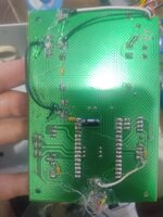
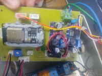
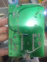
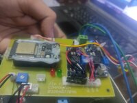
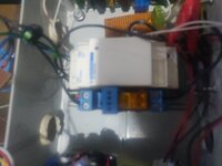
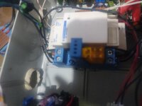
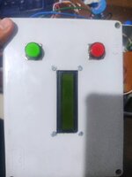
I try to drive electromagnetic contactor with esp32 controller and display some data on JHD 2x16 i2c (pcf8574)lcd. An d 2 button for some function.
For this i schematic and made pcb.
But issue is that when electromagnetic contactor on or off . My circuit is disturb.moslty lcd start showing garbage and some time my esp32 controller hang.
For this try so many thing.
1- For connect Pcb board to i2c module use shielded wire.
2- add 0.1uf and 1 uf capacitor near to lcd and controller supply pins.
3- add 0.1 uf capacitor every input and output pins.
4- use 5v to 5v dc to dc isolated module for separate esp32 and lcd supply.
5- use copper pour hatch ground all over tha pcb and attach to external ground.
6- i use ferrid core ring in input and output wire.
But noise still come in board..
For electromagnetic contactor i drive 5 volt relay which drive 220 volt relay who operate contactor.
Kindly guide me what i doing wrong .
I think i need to design pcb again. For this give suggestions.
 

Attachments

  • IMG_20231029_180202.jpg
    IMG_20231029_180202.jpg
    1.3 MB · Views: 81
  • IMG_20231029_180157.jpg
    IMG_20231029_180157.jpg
    1.4 MB · Views: 65
  • IMG_20231029_180204.jpg
    IMG_20231029_180204.jpg
    1.3 MB · Views: 79
  • IMG_20231029_180211.jpg
    IMG_20231029_180211.jpg
    826.5 KB · Views: 56
  • IMG_20231029_180256.jpg
    IMG_20231029_180256.jpg
    4.3 MB · Views: 70
  • IMG_20231029_180251.jpg
    IMG_20231029_180251.jpg
    4.2 MB · Views: 67
  • IMG_20231029_180310.jpg
    IMG_20231029_180310.jpg
    1.5 MB · Views: 70
Hi,

no wonder it fails.

I see no solid GND plane.
I see no proper supply bypassing.
I see no EMCompliant PCB design.

So it´s expectable that noise either coupled via power supplies or via signal lines causing the microcontroller to hang.

A PCB layout is more than "just connecting pins". Some 10 years ago this may have worked, but now the devices as well as the signals are much faster.
Faster signal edges causes higher EMI .. while faster devices are more sensitive to EMI noise.

Klaus
 
Hi kalus thanks to replay.
U said solid plane. For this u mean plane top copper side. ?
I make one side pcb that is why i draw pour on bottom side and connect to external ground.
Proper bypass
And
EM compliant circuit desing
kindly guide me for this.
I have not much experience in professional industrial circuit designing. That is why
I need tip and hint related to EMI and power surge noise .
 
Adding to what Klaus stated, can you post a schematic for us. The photographs don't show anything to trap back-EMF from relay coils or indicate the load the relays may be placing on the ESP32.

For reference, I have ESP32s driving large relays in water pumping stations that work 24/7 without any problems and they do also drive LCD modules and communicate by WiFi so it is possible to do.

Brian.
 
EM compliant circuit desing
kindly guide me for this.
I have not much experience in professional industrial circuit designing. That is why
I need tip and hint related to EMI and power surge noise .
If it was that easy to teach within a couple of forum posts .. I would not have needed decades of experience. ;-)

I recommend to do one (or more) of the many EMI compliant PCB routing tutorials.
Then - in case - ask more detailed questions.

Regarding GND plane:
A simple copper pour is no to compare with a solid GND plane.
--> For beginners I recommend to use one layer as solid GND - nothing else. Connect every device´s GND with short paths to the plane.

.. later .. if you are more experienced and know what GND_loops are, how their length matters, how their enclosed are matters you can do EMC compliant PCB layouts with single layer (but it is way more difficult than with just a pure GND layer).

I´ve done some examples on how to improve PCB layout here in this forum. Do a search.
I don´t have the links/threads by hand.

And please don´t post 15MBytes of blury photos. Mind that this is an international forum and there are places with low internet bandwidth. On every PC, most cellular phones and online there are tools available to decrease photo file size (to less than 10%) without losing thread topic related informations.

Klaus.
 
Last edited:
Hi,

Yes, I understand what you're saying. Thanks for guiding me. I've redrawn the complete circuit. First, I'll post the schematic, and then I'll start PCB routing.

I've redrawn everything for practice and learning. Kindly take a look at my schematic and guide me regarding EMI noise and how to secure digital communication lines like I2C.

After this, I'll start PCB routing
 

Attachments

  • esp32_airFlow.PDF
    51.7 KB · Views: 77
I'm guessing the ESP32 in your schematic is really a development PCB rather than the IC itself.

The first problem I can see is the power supply, the ESP32 can consume quite a lot of current, especially if the WiFi transmitter turns on. I see almost 300mA at times but the RE0505S is only rated up to 200mA. You could be seeing the supply dropping out. The 5V PSU also runs close to capacity if all the inputs and the SSRs are turned on simultaneously.

Second problem: again I'm having to guess but if RV1 is setting some voltage for the ADC to read, it needs a capacitor from the wiper to ground, especially if it is mounted more than a few cm away.

Third problem: The "adc1" line needs a pull-down resistor to ground and possibly also a capacitor to ground. If left floating it will read random values.

Fourth problem, the I2C lines need pull-up resistors to supply, suggest 4K7 on each line. If you are expecting to connect to 5V I2C devices I would suggest adding a voltage level translator between the ESP32's 3V3 and external 5V connection. There are IC to do this or you can do it with a couple of small MOSFETS and resistors.

I suspect your biggest problem is layout though, long wires are your enemy and try to avoid loops in the ground wiring that could cause voltage drops at the analog or digital inputs to the ESP.

Brian.
 
Hi,

Somevery basics are unclear.
* where do the 24V come from?
* there is a mix of Earth_symbols and GND_signals Are they isolated or connected? Make it clear in your schematic.

As already mentioned:
* relays (coil) need free wheeling diodes

Also:
Every signal follows a loop. There is no single signal from A to B. There always is the according return path. Route them in close proximity so that the magnetic fields compensate. Especially when high currents or high voltage_rise_rate is involved (relay contacts for example).
Don't use one connector for the signal and a different connector for the return path.

Every signal that leaves/enters the PCB should have an RF (EMI) filter and ESD protection according the expectable error signals.

Klaus
 
-> 24V supply: An external supply is used, which is the supply of another discrete IC card where I obtain analog signals. Earlier, I operated the main controller board using this 24V supply, but now I'm using the HLKPM01 220 to 5V module.

-> I'm trying to isolate the controller and digital circuit supply using a DC to SC converter (RE0505S). Everything connected to the external circuitry uses the GROUND symbol, and for the internally isolated ground, I use GND. Similarly, I isolate V5 with inner_V5.

-> For the output, I'm now using a 5-volt Solid State Relay, and to drive the 220V AC relay, should I connect a diode to the 220V relay?
 
Hi,

GND:
There is a connector "analog input". It shows the 24V_GND symbol, but the microcontroller_ADC refers to 5V_GND ... this won't work.

Solid state relay: use a transistor (BJT) as driver, but run the relay from 5V. No optocoupler needed.
Both 5V and 3.3V supply need to refer to the same GND.

Isolate only where you need isolation.
Use optocouplers only between isolated systems.

Klaus
 
Not all capacitors are equal in performance, ESR, for same C. Polymer tants best for bulk,
ceramics for HF bypass :

1698844772367.png


OS-CON is polymer tant.

If you have a DSO put it on on one shot/single sweep, and set it for level trigger, ~ 1V above
ESP32 supply rail, probe pins, and -1V below ground and repeat looking at pins. See if you
can find a specific pin that seems to have out of spec transient levels applied to it.

Proper probing : https://www.tek.com/en/documents/whitepaper/abcs-probes-primer

Regards, Dana.
 
Last edited:
Yes, I tried to isolate the ground with the microcontroller, but for the ADC, I must use the same GND. This is a confusing issue, and I don't have a solution for this.

Earlier, I used an SSR module which had a BJT transistor but it didn't work with a 3.3V signal. That's why I used an optocoupler as a transistor and isolation medium, and I have separate outer ground and inner ground.

I've isolated everything except for the ADC ground.

Are there any other components I need to add for better filtration?

Can you recommend an EMI filter and an ESD diode component that is best for a 5V circuit?
 
Hi,
Yes, I tried to isolate the ground with the microcontroller, but for the ADC, I must use the same GND. This is a confusing issue, and I don't have a solution for this.
Again: Isolate only if you need it. Tell us the reason.

SSR module which had a BJT transistor but it didn't work with a 3.3V signal.
Read what I´ve written. The BJT works well with a 3.3V signal, the SSR works well with a 5V supply.

Are there any other components I need to add for better filtration?
To be "better" you need to have one in first place, but I don´t see any.
The simplest HF filter is a capacitor. As others said, use them at the inputs. Especially at those who are sensitive on noise. Mainly (analog) ADC inputs, but also every edge sensitive digital input (RESET, Interrupt, interface...).

A single capacitor has to rely on source impedance.. better to add a series R to get calculable delay / cutoff frequencies. Formulas like:
* tau = R * C
* fc = 1 / ( 2 * Pi * R * C)
should be standard for every electronician to know.

Can you recommend an EMI filter and an ESD diode component that is best for a 5V circuit?
Go to your distributor and do a search for "ESD protection". There are many different ones. THM, SMD, multiple devices in one package...
Mind: 5V protection devices are inactive for 5V signals, they become active beyond 5V. If this "beyond 5V" is over the specified voltage of your microcontroller (or any other device) then you need to add a current limiting resistor.

Klaus
 
A lot of guessing occurs if you are unable to look at signals / pins with a scope,

The LM2596 modules have issues : https://e2e.ti.com/support/power-ma...djevm-lm2596s-adjevm-discontinuous-mode-noise

Google https://duckduckgo.com/?q=dana+pcb+layout+pdf&ia=web lots of ref material on PCB
layout.

When probing if supplies non isolated you can easily damage a scope, this will help :


Attached a discussion on layout, focus switchers but general principles apply.


Regards, Dana.
 

Attachments

  • Meeting Power Design Challenges 2007 National Semiconductor Seminar.pdf
    1.5 MB · Views: 53
Thank you for guiding me.

I use an optocoupler for every digital input and output. The reason is to isolate the main controller board from the external circuit.

Basically, my controller card reads and controls a machine that has a magnetic conductor and an AC induction motor. Everything is enclosed in a metal body, including my circuit. So, my goal is to achieve full electrical and mechanical isolation for the main controller card and the machine. For this purpose, I use optocouplers and DC-to-DC converters.

I also prefer using optocouplers over BJT (Bipolar Junction Transistor).

I need more guidance about ferrite beads and ESD (Electrostatic Discharge) because I have never used them before.

I have updated my schematic to include a snubber circuit on the SSR (Solid State Relay) output and a varistor in the 220V input.

Another question I have is whether I should use TVS (Transient Voltage Suppressor) on the I2C and Serial TX/RX lines?


Hi,

Again: Isolate only if you need it. Tell us the reason.


Read what I´ve written. The BJT works well with a 3.3V signal, the SSR works well with a 5V supply.


To be "better" you need to have one in first place, but I don´t see any.
The simplest HF filter is a capacitor. As others said, use them at the inputs. Especially at those who are sensitive on noise. Mainly (analog) ADC inputs, but also every edge sensitive digital input (RESET, Interrupt, interface...).

A single capacitor has to rely on source impedance.. better to add a series R to get calculable delay / cutoff frequencies. Formulas like:
* tau = R * C
* fc = 1 / ( 2 * Pi * R * C)
should be standard for every electronician to know.


Go to your distributor and do a search for "ESD protection". There are many different ones. THM, SMD, multiple devices in one package...
Mind: 5V protection devices are inactive for 5V signals, they become active beyond 5V. If this "beyond 5V" is over the specified voltage of your microcontroller (or any other device) then you need to add a current limiting resistor.

Klaus
 

Attachments

  • esp32_airFlow.PDF
    52.8 KB · Views: 57
Hi,

You give no reason "why" you need isolation.
You are free to do so.

I can just say that I have decades of experience designing professional reliable electronics for high power chemical industry.
They run 24/7. A fail in the seconds will destroy a production batch worth 50k US$.
They control load up to 2000V RMS and they regulate currents up to 3000A RMS using SCRs.
They don't fail.

I use optocouplers where they are necessary ...
... but I also had troubles with them ... failing after long term usage by degrading performance.
This was in my early designer days ... since then I know how to treat / avoid them.
Besides isolation - I don't see a single benefit of optocouplers against BJTs. But they degrade, use more space, are more costly...

I need more guidance about ferrite beads and ESD (Electrostatic Discharge) because I have never used them before.
Every manufacturer provides loads of documents. From basic informations to detailed design notes.
This is more than we can give in a forum thread.
Please use them, read through them ... an in case ask detailed questions here.

"I have never used them before" .. is a daily event for designers.... nothing special ;-)
I recommend to read datasheets and other informations provided by the manufacturers. This is my daily routine, this is where I have my knowledge from.

Snubber: Who told you to use them? I mean they may be useful ... but I wonder why you do things that I can´t find being recommended while other recommended things you ignore.
Datasheet tells it already includes the snubber.

Tx/Rx: you say everyting is in a metal box. Then I wonder what they are used for. Not saying it´s impossible.
But usually they connect to "the outside world". We don´t know unless you tell us.


Klaus
 
Hi, I appreciate your answer. You are right about everything. The optocoupler is not reliable for a long time. On my side, I have no issue with the price, and it's not for a highly sensitive machine. My concern is only electromagnetic noise.

So, this time I found the problem. It's the 5V relay that I use in my circuit. When I remove it, it solves 90% of the hanging issues. I replaced it with a 5V SSR. I redesigned the PCB for this, and I'll show you. If the PCB routing finds anything wrong, please educate me.

Sorry for the late reply; I was busy with some work
 

Attachments

  • esp32_airFlow.PDF
    52.8 KB · Views: 68
  • esp32_airFlow_ok.PDF
    135.3 KB · Views: 72
yes i know , its low stander design , i have some limitation , i draw only one side pcb bcz of local manufacture not able to print double side, and i use module bcz of easy solution, i have one question , i have 2 gournd one is for outside of controller and one is innternal controller, so i use PCB pour, around the outside the of controller is use extrenal ground Pour , and in esp32 module us internal Ground pour, its that right way?
 
Hi,

I agree with Brian: If it works for you...

It´s a question of what you are happy with. I surely would not be happy with a solution that reduced the hang rate from 100% down to 10%.
Usually my devices don´t hang at all.. but if there was one, then I usually generate code to doe some kind of "stress test and debugging" to find the source of the problem. I don´t like curing the symptom.

But I hope you don´t mind my honest words:
I don´t see that you followed a single of my recommendations.
So if you want my opinion about your current schematic and PCB, just re read all my posts above.

Klaus
 
Last edited:

LaTeX Commands Quick-Menu:

Similar threads

Part and Inventory Search

Welcome to EDABoard.com

Sponsor

Back
Top