KhaledOsmani
Full Member level 6
Hello
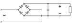
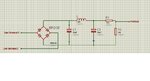
Im using a single phase full wave bridge rectifier made of four diode connected as shown in Fig(a).
The input is an AC voltage source of 120Volts.
When I`m branching the voltmeter at the terminals of the 100uF electrolytic capacitor, and switch the voltmeter to AC mode, it keeps outputting AC voltage!
the AC voltage should be rectified and no AC components must be there, how come I still read an AC voltage on its output? Could it be that there are harmonics on the output, and the voltmeter reads them, contrarily to a DC motor that takes the average value of the rectified output?
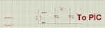
Should I add any type of filter on the output terminals, so that I can get a pure DC signal?
I`m intending to input the rectified voltage, after making voltage division, to a digital system. aren't these AC voltages would harm the digital system?
- - - Updated - - -
the diodes used are 1N4007 and the capacitor in parallel is of value of 100uF
Im using a single phase full wave bridge rectifier made of four diode connected as shown in Fig(a).
The input is an AC voltage source of 120Volts.
When I`m branching the voltmeter at the terminals of the 100uF electrolytic capacitor, and switch the voltmeter to AC mode, it keeps outputting AC voltage!
the AC voltage should be rectified and no AC components must be there, how come I still read an AC voltage on its output? Could it be that there are harmonics on the output, and the voltmeter reads them, contrarily to a DC motor that takes the average value of the rectified output?
Should I add any type of filter on the output terminals, so that I can get a pure DC signal?
I`m intending to input the rectified voltage, after making voltage division, to a digital system. aren't these AC voltages would harm the digital system?
- - - Updated - - -
the diodes used are 1N4007 and the capacitor in parallel is of value of 100uF