Continue to Site

Welcome to EDAboard.com

Welcome to our site! EDAboard.com is an international Electronics Discussion Forum focused on EDA software, circuits, schematics, books, theory, papers, asic, pld, 8051, DSP, Network, RF, Analog Design, PCB, Service Manuals... and a whole lot more! To participate you need to register. Registration is free. Click here to register now.

Diode bridge rectifier, single phase, full wave, rippled output

Status
Not open for further replies.
So be it! I hope they have a plentiful source of PICs - and a forgiving telco - and wear insulated shoes while working on it :lol:

Brad - the power source is a telephone line, not 50/60Hz mains AC.

Brian.
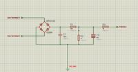
 
Brad - the power source is a telephone line, not 50/60Hz mains AC.

Thanks, the schematic (with those 20 mF capacitors) made my mind think 'everyday power supply'.

It slipped my mind that it's to power a load during a ring signal which contains AC.

Those capacitors will need a minute or two to charge from a telephone line.
 

So such a project cannot be electronically done?

@betwixt I don't intend to branch the system on the line terminals all day, the test would take only to maximum 40 seconds, where I previously disconnect all loads from it. i.e modems, approved phones, all possible loads for a landline.

I would take the initial two terminals directly from the cable.

No fault would occur neither banning from telco.

If i apply a regular multimeter and see the voltage between the two terminals, as 53V DC this means that the line is functionning good. Thats it.

I just want to apply a small LCD telling the technician that it is working good, regardless from showing the voltage.

The 12VAC is square-wave formed that peaks only when the telephone rings.
 

L, C1, C2 together resonate at 48 Hz. This could lead to oscillations which can get out of hand (more so if incoming mains is 50 Hz). Destruction of components is possible.

There are two-stage capacitor filters, which have a resistor where you have L. You will not get resonance with such a filter. It would require experimentation to find a satisfactory combination of values.

Assuming that the incoming mains is of 100 Hz.

For such an LC filter, the resonant frequency = 1/2*pi*squareroot(L*C)

If I set the circuit to resonate at 500Hz (which can never be achieved by the mains) for maximum protection, so @ 500 Hz the reactances would be equal and all impedances are cancelled: shortcircuit act.

If Fresonant is set to be on 500Hz accordingly with the 20mF electro. Capacitor, the L value would be of almost 5uH.

In this case of filter design, would any hazardeous still there and might be possible ways of component damage?

As for the filter with R instead of L in between shunt capacitors, does it have same schematic as LC filter?
Double staged, you mean by this that the same initial RC circuit must be repeated two times?

After all, do you agree about the value of capacitors of 20mF??

Since I added thanks to Audioguru a 10mF smoothing capacitor, and saw a great improvement about vanishing the ripples, I thought to double the capacitance, to vanish even more the ripples, or this is not logically correct?

About countries of architecthing landlines, here when a ring pulse occurs the signals do NOT superimposes.

I tried to connect directly the multimeter from the main distribution frame room on a landline, and called the number of this same landline, nothing was changed on the multimeter, still 53VDC

As to note, i would only connect this system on the terminals of the line for bunch of seconds to see after ADC the output written as words not voltages on a small LCD, sure thing after disconnecting the line from all loads.

Summary: if LC filter was chosen:
L = 5uH
C1=20mF
C2= 20mF
True or false?

If R instead of C, the capacitors would have the same capacitance, but i will need to make a serial trial and error (before connecting the PIC) to see the exact value of resistor that must be connected. True or false? What initial resistance should i start with?

Thanks
 

I'm still not clear about what this thing actually does. After more than a decade working on telecoms test systems in several countries, I have never come across one that disconnects the DC when applying the ringing voltage as it would significantly increase the costs in the switching network. Measuring 53V with and without the ringing suggests the voltage IS still there but your meter is seeing the average of 53V DC +/- ringing voltage which is of course still 53V.

However, the underlying problem is landlines work at constant current with a voltage limit. Its done that way so the wire resistance from the switch to the end user can vary considerably (because of the distance) while keeping performance almost the same. If you draw current to charge the capacitors in your rectifier circuit you will see a drop in voltage which will in turn activate the line as seen from the Telco end, it will think you have gone off-hook. There is an additional risk that of your Telco accepts pulse dialling, you actually call a number without realizing it!

If the purpose of this gadget is to test the line itself, there are simple methods to do a crude voltage, current and timing checks but you need to power the unit from a battery or an approved fully isolated power supply. As I stated before, you cannot connect anything between any circuit wired to the phone line, regardless of whether it has rectifiers or anything else, and any equipment that is connected to ground or any other DC potential. Not only does it violate Telco rules, it puts your equipment at risk from high voltages, especially if you are in an area prone to thunderstorms. In my history of working with test specifications, most Telco insist that equipment wired to the lines must withstand 1.5KV for 10 seconds across the insulation barrier without any breakdown or increase in leakage current. That is just the electical barrier, they then also insist on a further isolation between the electronics in the phone and any part that can be touched.

Brian.
 
Dear Brian:

The problem is that you are replying according to high accuracy and improved telco switching which is accorded to your country, which is dramastically different than the one in here.

Please forget all above, and check only this:

The PIC with the 2*16 LCD are supplied with a 9V lithium battery, then regulated with an LM7805 voltage regulator. The PiC circuit accordingly has a separated source.

Now as for the purpose of this system it works only as a voltage meter, after ADC on PORTA.0

The input voltage for PORTA.0 is got from the terminals of a landline, but NOT directly:

The landline is entered to a single phase full wave bridge rectifier, then the bridge output is supposed to an LC pi filter, to get rid of any noise, ripples, unwanted signals -if existed-
Then after the signal is filtered, a voltage divider of 100k / 10k is done, to make sure that the entered voltage to the pic is no more than 5V DC ( not to mention that there are voltage drops due to diode conduction)

After the signal is "neat", and less than 5V, an ADC is done by the PIC than DAC to outputs that on the LCD the current status of the line:
If 53V line is good
If 0V it is either conductor failing of one or two landline conductors orelse both conductors are faulty: line is not good.

Thats it.

The Lc filter component are as follows:
C=20mF (for both)
L=5uH.

If you still insist on the voltage superimposing when a call is in occupance, assume that this in my case dont exist.

About the off-hook, this wont happen when i plug the thing, since when u branch a multimeter to the two terminals of the landline, you dont get offhook.

That is all.
This thing branchment on the landline would occur only for bunch of seconds, to check what is written on the LCD.

Are things more clear now? Are values for components of LC filter are correct?
 

I understand what you are doing but I'm not sure you do!

If the intention is to measure the line voltage you certainly don't want an LC filter. Wire it like this:

Incoming line goes to a bridge.
Wire a SMALL capacitor across the DC output of the bridge. I suggest 100nF.
Connect the negative side of the bridge directly to the PIC GND pin.
Connect the positive side to a potential divider to drop the voltage to < VDD. Keep the resistor values in the range 100K to 10K if possible.
Wire a capacitor of say 10uF across the ground resistor of the divider.
Wire a 1K resistor between the 10uF capacitor and the ADC input pin. This is to protect the ADC input if you power down and there is still charge in the capacitor.
Power the PIC from the battery/regulator and do not make connections to any other equipment.

The intention is to keep the time constant at the ADC as short as possible while drawing as little current as possible from the line. If you want to measure the voltage in an off-hook situation, either connect a phone in parallel on the line and lift the handset or connect a 100mA constant current load across it.

Incidentaly, I have worked on testing telephone equipment and Telco switches for your country !

Brian.
 
Don't tell me, you trace-routed my ip, and knew my country :eek: ?
 

Ok.

Thanks for sharing your knowledge.
The LM7805 when input to a 9V silver battery, outputs a 5.5V instead of 5.
I always face this problem, even though I had connected to its input 0,33uF and output 0,1uF
Why?
 

There can only be one explanation for that - either your LM7805 is faulty or the meter is not accurate. The maximum a 7805 should output, at the top end of it's tolerance is 5.2V.

Brian.
 

Dear Khaled,
If you defined you problem in step 1 overall instead of just a measurement problem, a simple better solution would come forth.

Try to do that.

Define essential inputs to be measured and output response and power source preferred with all necessary other restrictions.
Right now it looks like a "wild goose chase" trying to define what is important you need.

Is it just a logic level out for CO battery V detect to show connection or ADC output to indicate Off hook too? Or ? .?
 
You got right.

You have an LM7805 alone.
at its input pin & ground is connected an 0,33uF electrolytic capacitor.
at its output pin & ground is connected a 0,1uF electrolytic capacitor.

The input is fed from a 9V battery.
When branching the multimeter one probe on the output pin, and the other probe at GND, I have to value of 5.5V.
It must be 5V, not 5,5V.
Why has that happened and how to fix it?
 

Why 5.5? Is anything pulling the output up? Like an LED to 9V
Otherwise fails spec.

Why 5V? If you really need an ADC, which I doubt, use a 3V uC and a CR123 Lithium cell, no regulator, or better yet , use microamps,and charge up from 50V with 10k.

Your Input output Ux specs are vague to me.

UX means user experience or expectations.
 
The ripple voltage is equal to the inverse of peak to average current in the capacitor. The load, R and value of C desired is chosen as a function of the charge interval T = 1/2f RC >> T and ultimately the % ripple is RC/T as long as the ESR of the CAP and source impedance is much lower than load R.

Thus for 10% ripple voltage RC=10T but average Vdc has dropped 5%.

What is your requirement?
 

@betwixt

I made the following circuit as input:

I have three cases for the landline: either it is working properly, either there is no tone at all, when you pickup, either and intermediate case, where there is a tone, but noise exist, and could be heard.

Now when I branch the multimeter, one probe to PORTA.0 and the other to GND, I get the following analog (voltage) results for each case: (different values are got from testing a different landline than the previous, it was a series of tests upon tens of different landlines)

When the line is working properly:
4.6V
4.6V
4.22V
4.29V
4.64V
4.49V
4.44V
4.64V
4.5V
4.48V
4.44V
4.24V
4.3V
4.49V
4.44V
4.45V
4.46V
4.64V
4.64V
4.47V
4.65V
4.44V
4.64V
4.65V
4.47V
4.54V
4.41V
4.53V

when the line is faulted (no tone can be heard when picked-up:
0V
0.04V
0.5V
0.99V
1.82V
1.83V
1.84V
1.85V
0V
0.53V
2.25V
2.33V
1.82V

when the line isworking but has a remarkable noisy sound:
4.09V
4.1V
4.11V
4.12V
4.13V
4.22V
4.33V
4.21V
4.44V

Now if we apply the ADC on PIC basic, to get the discrete values (PIC18F4520, 10-BIT resolution):

X = 1024 * voltage / 5

The following was my code:
Code:
ASM:        org 0x800
Define LCD_BITS = 8  
Define LCD_DREG = PORTC
Define LCD_DBIT = 0  
Define LCD_RSREG = PORTD
Define LCD_RSBIT = 3
Define LCD_EREG = PORTD
Define LCD_EBIT = 5
Define LCD_RWREG = PORTD  
Define LCD_RWBIT = 4  
Define LCD_COMMANDUS = 2000 
Define LCD_DATAUS = 100 
Define LCD_INITMS = 100  

Dim volt As Word

ADCON1 = 0x0e  
Lcdinit 1 
here:

Lcdcmdout LcdClear
	Low PORTD.0
	Low PORTD.1
	Low PORTD.2
	Lcdout "Connect Line"
	WaitMs 800
	
If PORTB.7 = 0 Then
Goto there
Else
Goto here
Endif

there:
			Lcdcmdout LcdClear
			Adcin 0, volt
			WaitMs 200
ok:
	
		If volt > 880 Then
			Lcdcmdout LcdClear
			Lcdout "Line is: OK"
			High PORTD.2
			WaitMs 800
			If PORTB.7 = 0 Then
Goto here
Else
					Goto ok
				Endif
		Endif
		
boucle:
		If volt = 0 Then
			Lcdcmdout LcdClear
			Lcdout "Line is: BOUCLE"
			High PORTD.0
			WaitMs 800
			If PORTB.7 = 0 Then
Goto here
Else
					Goto boucle
			Endif
		Endif
				
occuped:
		If volt > 128 And volt < 133 Then
			Lcdcmdout LcdClear
			Lcdout "Line is: BUSY"
			High PORTD.0
			WaitMs 800
			If PORTB.7 = 0 Then
Goto here
Else
					Goto occuped
			Endif
		Endif

In the above code, the circuit, tells the user, on the LCD to branch the terminals of the landline, then to press the pushbutton on portb.7 to inform the circuit that the line is connected.

After the Line is connected an ADC process is done, and according the the volts values, the if/else conditions defines what states corresponds to the line connected and blink a LED accordingly.

THE FOLLOWING IS THE ONLY PROBLEM:

Sometimes, the line would show a results of working properly but in fact the line is having a noisy sound on it. This is because sometimes the noise state of a line (not clear tone) could have the same voltage value of a working line.

The followings were written as notes:
1) when the line is OK:
it has a time constant voltage value as shown previously (generally from 4.22V to 4.6V)
2) when is line is faulted, no tone is there:
it has a time constant voltage value (from 0 to 2.5V)
3) when the line is working but has noise (not neat):

it might have a voltage value of a properly working line, and also different values, that could take place in the faulted case, and also other values floating, but the only difference is that this value is not time constant and changes fastly from a value to another in an also not constant time

For example, when the line is noisy, it have voltage values, of 4V then 4.22V then 4.31V then 4.36V then 4.11V in T = 23 seconds.

another line with same state, have the voltage floating values from 4 to 4.37V in T = 5 seconds.

I thought to input a timer in the code, such that it separates the working line case from the noisy case.

Any suggestions?
 

I understand how the schematic works and what you are doing in software but it isn't clear what the purpose of the device is. The bridge rectifier is there because it may not be possible to tell the polarity of the incoming line but it will not rectify 'noise' and give you a measurement of it. Just measuring the DC on the line will not give a maeningful indication of whether noise is present, especially as there is already filtering due to the two capacitors. Your circuit is also prone to damaging the ADC input when ringing voltage is put on the line. It will charge C1 up to potentially > 100V so even after the divide by 11 resistors it could easily exceed the ADC pin limit.

What exactly are you trying to measure? on-hook voltage, off-hook voltage, open circuit line, line noise, dialtone level? If it is noise, you need to explain the kind of noise it is.

Brian.
 
What exactly are you trying to measure? on-hook voltage, off-hook voltage, open circuit line, line noise, dialtone level? If it is noise, you need to explain the kind of noise it is.

Brian.

All above.

What I mean by noise is, suppose you have a DSL connection, where you didn't put any DSL filter when using your landline phone. You will hear a buzz when you speak on the phone. This is what I mean by noise.
 

I think you are going about solving this problem the wrong way. The level of 'noise' you refer to is only a few mV superimposed on tens of volts DC and because you have no ground reference the chances are you will inject more noise from the measuring crcuit than is there already. You can certainly measure the line voltage using your method although not very accurately but to measure signal levels, whether the wanted ones or 'noise' you really have to isolate them from the DC first. Basically, you need a telephone with something that measures the voltage across the earpeice. If you specifically want to measure DSL signals you also need filters to split the frequency spectrum and amplifiers to bring the very low ADSL carier levels up to something an ADC can measure. Ideally, you need an isolating capacitor to block the DC and a transformer to isolate the voltages you are trying to measure.

Brian.
 
Status
Not open for further replies.

Part and Inventory Search

Welcome to EDABoard.com

Sponsor

Back
Top