Vermes
Advanced Member level 4

It is a design for everyone who want to use CPLD instead of for example expensive and complex FPGA. The simplest version is Xilinx XC9536XL. In order to use its all features, you should have a development board with pins and programmer. This board is relatively expensive, so it is better to make your own version. The same situation with the programmer for USB – when you are the ower of an old PC with LPT port, you can easily build a cheap programmer for parallel port.
Design of the board and programmer is based on this one: LINK.
The board can work with both XC9536 and XC9572 (version CPLD 44 pin).
They are versions of circuits powered from 5V. Circuits with XL have to be powered from up to 3,3V, although the supported voltage at the input pins can have a value up to 5V.
Presented here design has some additional advantages:
Programmer:
- has enlarged pads for port DB-25
- has added joint for programming 2x5 pin (it protects against inverse connecting the cable)
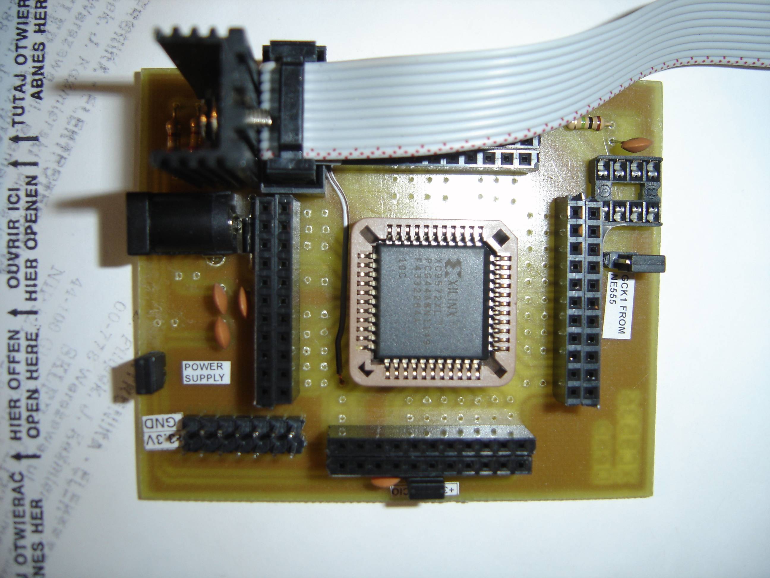
Development board:
- has changed supply (from 7805 to selectable output voltage power supply LM3117 + mountings for the heat sink – when it is powered from 9/12V, it loses greater power)
- a joint was added for programming 2x5 pin (it protects against inverse connecting the cable)
- each pin of the circuit is in two versions: standard (not secured) and secured (in series by resistor 330). It protects against accidental short-circuit (such as during incorrectly written load) and allows the cooperation with voltage degrees 5V at the inputs, by limiting the current of clamp diodes. Without the resistors inputs would be burnt in a short time
- adding few pins of voltage and ground
Design in Eagle, before etching:
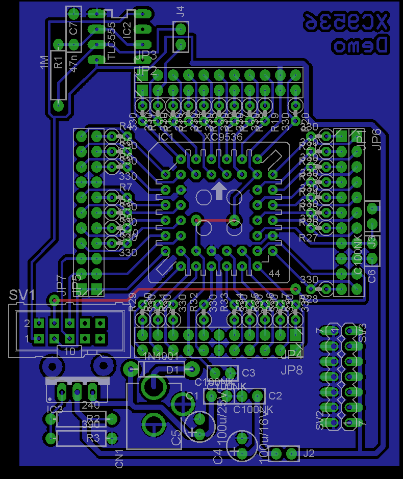

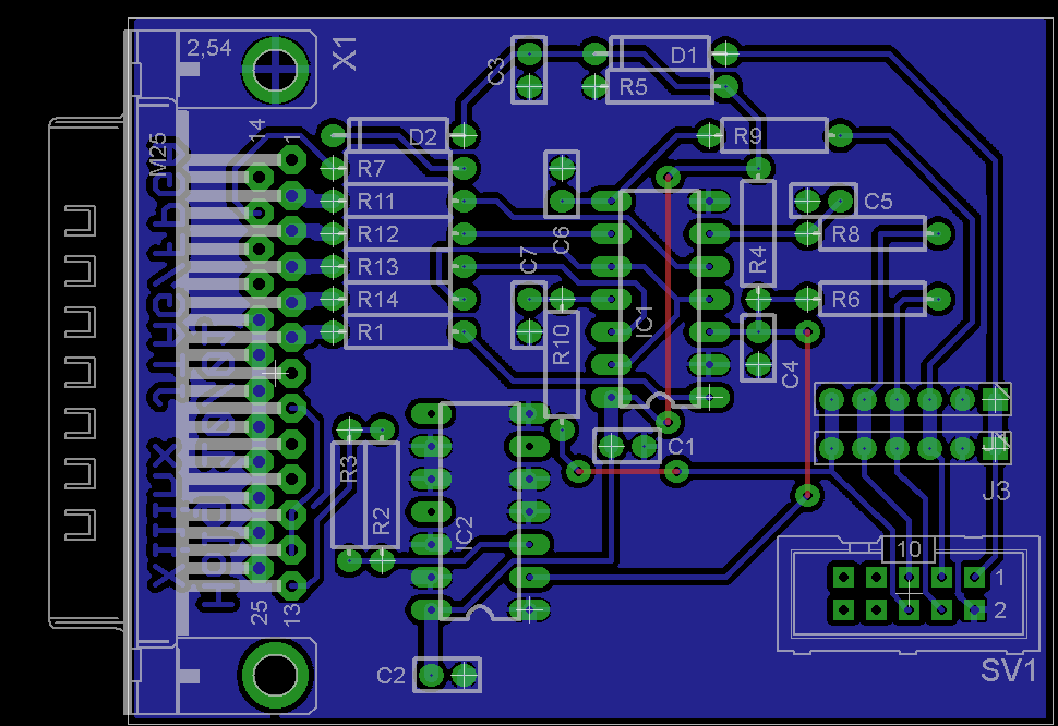 **broken link removed**
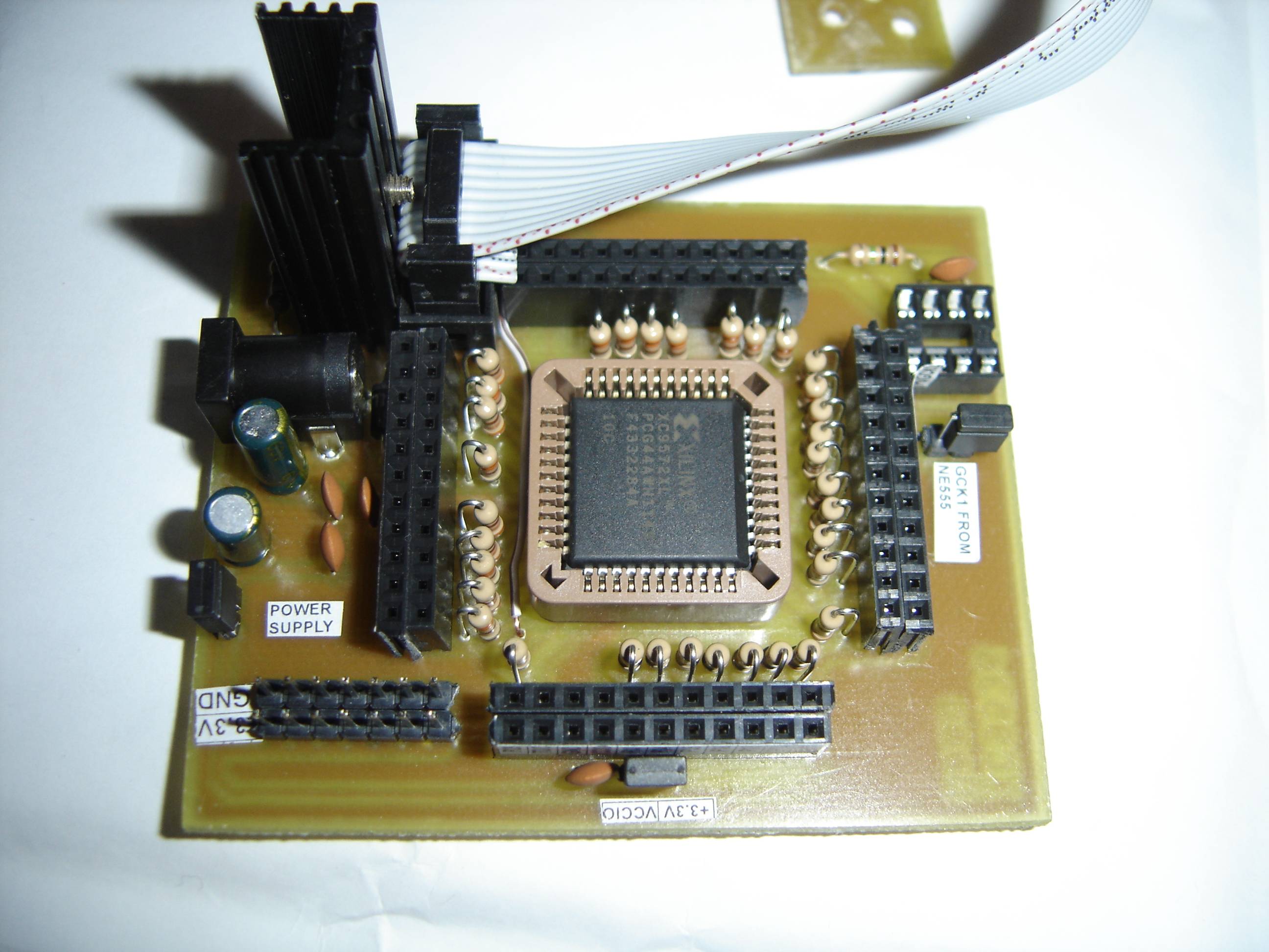
Before soldering resistors:
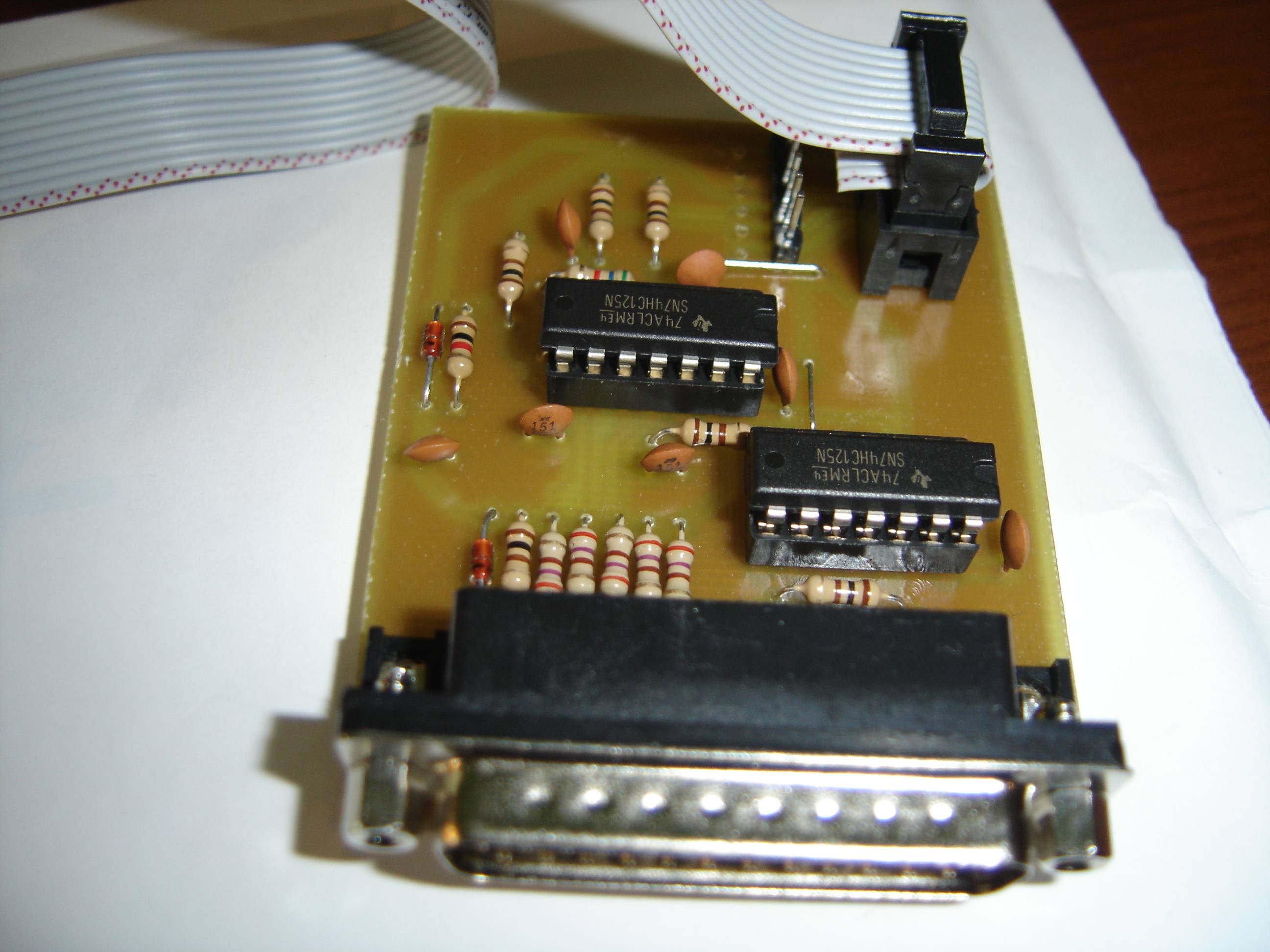

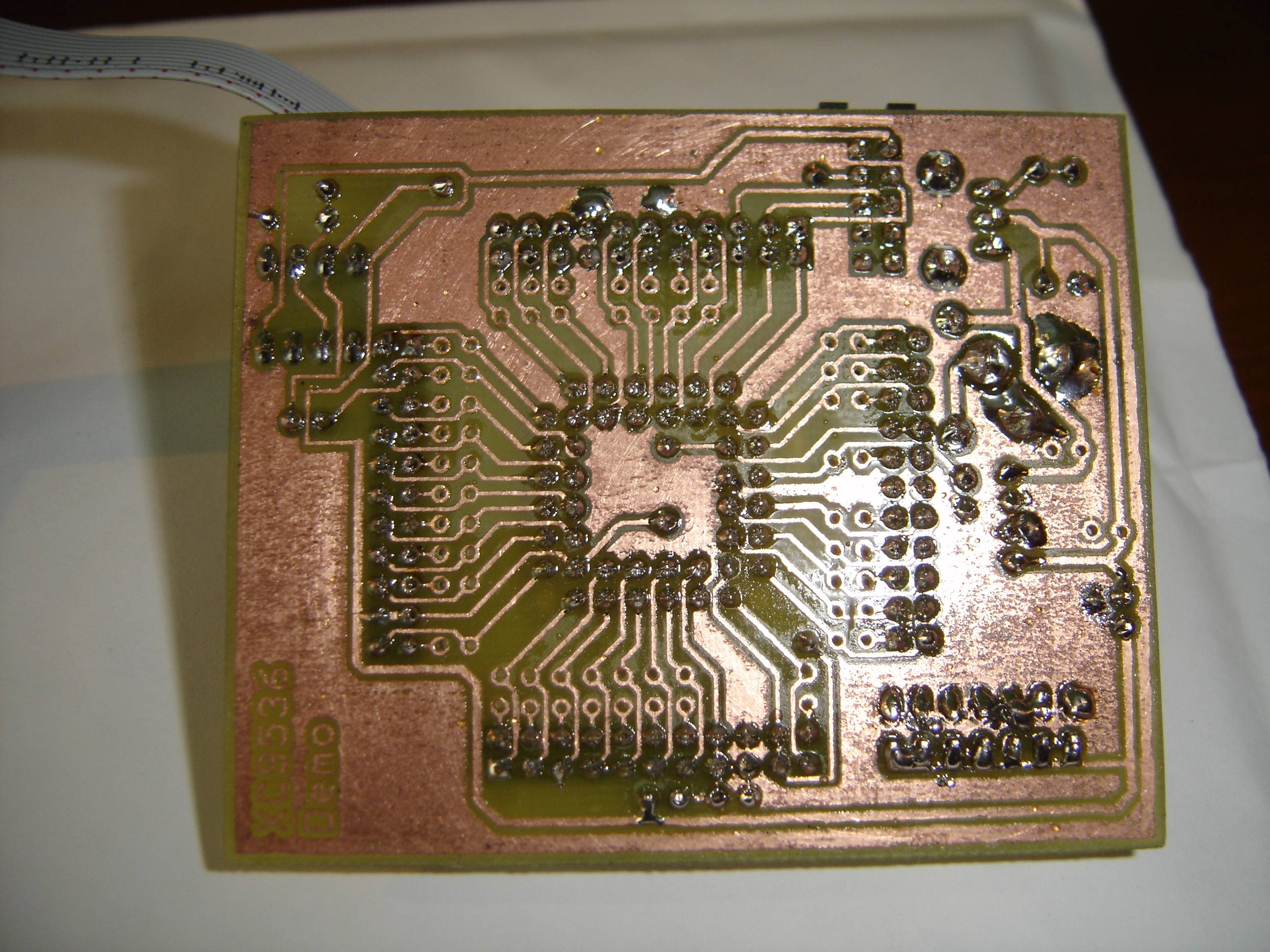
After soldering resistors:
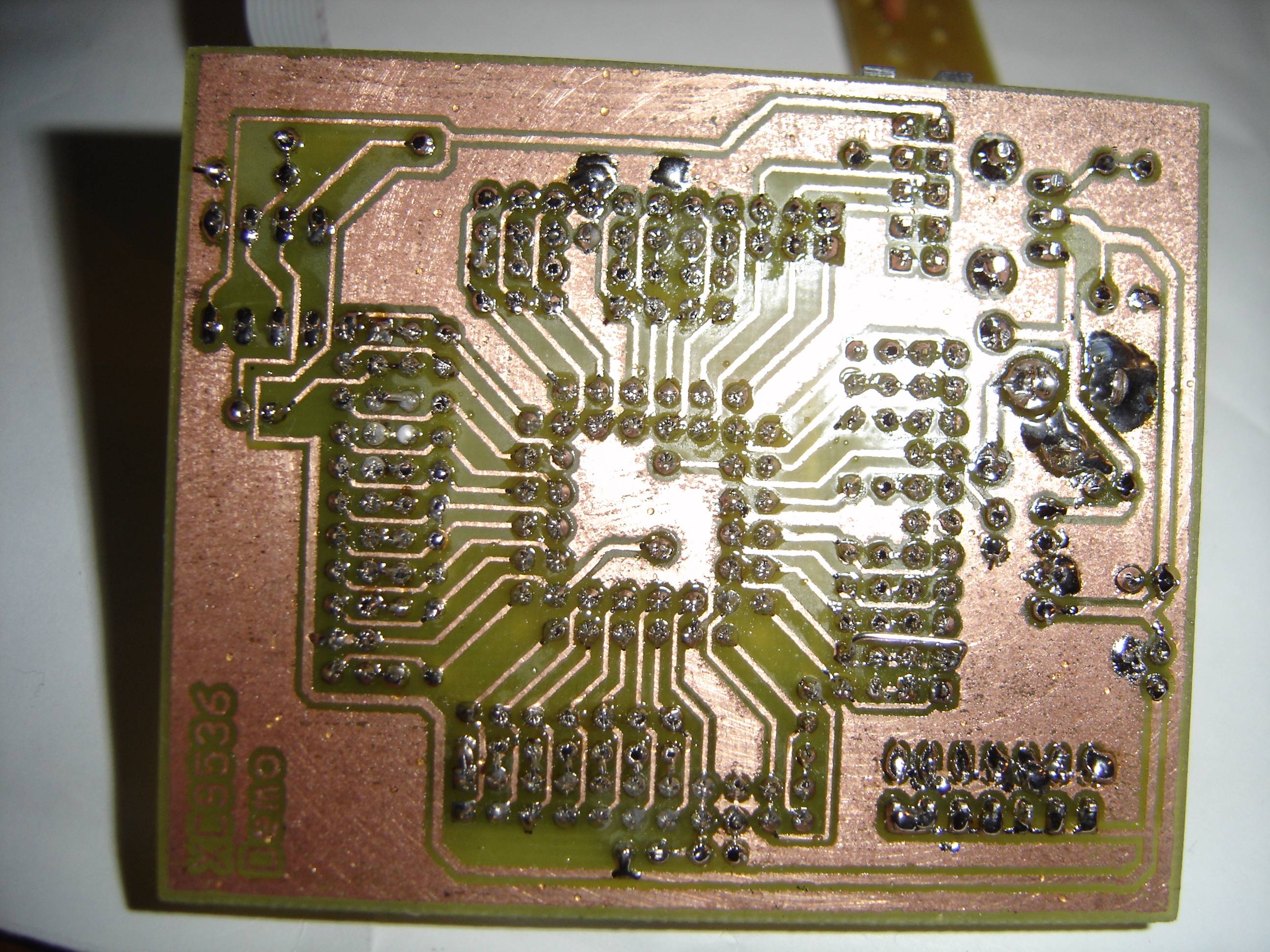
As you can see, that required drilling a number of holes.
Note that the metal housing of stabilizer LM3117 is connected to the voltage output, so do not solder the heat sink pads to the ground, or you will cause a short-circuit.
Link to original thread (useful attachment) - Płytka uruchomieniowa pod CPLD Xilinx XC9536XL/XC9572XL