Continue to Site

Welcome to EDAboard.com

Welcome to our site! EDAboard.com is an international Electronics Discussion Forum focused on EDA software, circuits, schematics, books, theory, papers, asic, pld, 8051, DSP, Network, RF, Analog Design, PCB, Service Manuals... and a whole lot more! To participate you need to register. Registration is free. Click here to register now.

Designing a preamp for photodiode, signals are lost

Status
Not open for further replies.

subha98

Newbie level 5
Joined
Mar 8, 2010
Messages
8
Helped
0
Reputation
0
Reaction score
0
Trophy points
1,281
Location
Ann Arbor
Activity points
1,339
Hi,

I am designing a preamp for photodiode. I ac couple the signal from diode and feed into transimpedance amp. but when I provide a DC leakage current path through a high valued resistor to ground,my signals are lost.
Why does providing a DC leakage current path to ground does not work for higher values of leakage current?
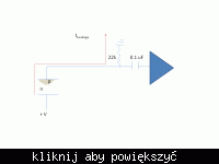
 

Leakage current path

Hi,
Maybe you have much surface leakage! Use guarding technique!
Good info source is for in 6th Eddition:"Low Level Measurements" a book (& 2-3 others too) from Keithley, you can order it free & over Webside:)...
Some circuits technique is descripted by ADI & older BurrBrown literatures(yet TI)...
What about over leakage in coupling capacitor?
Second source of your signal lost is maybe the bandwidth limitation through (very)high resistances & stray capacitances!
You can check for a feedback realized as a "T" structure...Described(I belive)in TI`s ApplNotes.
K.
 

Re: Leakage current path

subha98 said:
Hi,

I am designing a preamp for photodiode. I ac couple the signal from diode and feed into transimpedance amp. but when I provide a DC leakage current path through a high valued resistor to ground,my signals are lost.
Why does providing a DC leakage current path to ground does not work for higher values of leakage current?

I cannot visualise what you are describing. A circuit diagram would probably help.

Keith
 

Leakage current path

I think the diode is biased over a serial res. & so comes with AC-coupling to the amp, but a circuit will be better to see...
K.
 

Re: Leakage current path

depends on your diode, but high speed photodiodes like to be reverse biased to work right. A leakage path would bleed off the reverse bias?
 

Re: Leakage current path

The diode is reverse biased. Yes, the leakage current does limit the biasing that can be applied although the resulting bias voltage should be enough to generate a signal upon interaction.
 

Leakage current path

What provides the DC bias point for the amplifier?

Keith.
 

Re: Leakage current path

DC power supply for the amp is external(+5v) and is diferent from the diode bias supply, which a lot higher ( upto 50V)
 

Leakage current path

That doesn't explain what the transimpedance amplifier circuit looks like and where the input bias current for it comes from. It is difficult to help with so little information.

Keith.
 

Leakage current path

The TIA I use is SFT-0100 and works fine without the DC path resistor. My question is regarding this 22K resistor..is it causing a discontinuity that it is reflecting the high freq. components of the pulse, and hence TIA is not able to sense the smaller signal? How does increase in leakage current ( which is a DC current with some modulation) affect things further.
 

Leakage current path

I am still struggling to understand what you are doing. I am surprised you don't have a proper diagram to show. Your connection diagram, such as it is, shows no DC path for the photodiode except the 22k resistor. As the TIA is an 8GHz device I would expect it to either be connected directly to the TIA input, or to have its own load resistor of maybe 50 ohms.

You cannot really go coupling 8GHz through a 0.1uF capacitor - at best it will look like an inductor above a few MHz.

Keith.
 

Leakage current path

Its a ultra high BW coupling cap of pass band os 100KHz to 16 KHz. Anyway thanks.

Added after 40 seconds:

Iam sorry for the typo...pass band till 16GHz.
 

Re: Leakage current path

subha98 said:
Its a ultra high BW coupling cap of pass band os 100KHz to 16 KHz. Anyway thanks.

Added after 40 seconds:

Iam sorry for the typo...pass band till 16GHz.

A 16GHz 100nF capacitor? I would be interested in the details of that.

You didn't reply to my other comments.

Keith
 

Leakage current path

Hi Keith,
I was supressed too, but (I think) past week gave somebody on another topic a link over such AVX types, after that I found from AVX & ATC datasheets(maybe their are only from ATC)...
It exists only as 100nF!:)
K.
 

Leakage current path

karesz,

Thanks. I dread to think how much they cost! I usually end up having to parallel a few smaller capacitors to get good HF performance (although don't usually need 100nF at 1GHz!). Even "normal" microwave capacitors can be expensive.

Keith.
 

Leakage current path

:)
I think the more old school (more values parallel) is better of HF quality, but need more plaace...
K.
 

Re: Leakage current path

karesz said:
:)
I think the more old school (more values parallel) is better of HF quality, but need more plaace...
K.

It may be "old school" but normal capacitor cost = 0.02 UK pounds, microwave capacitor = 0.68 UK pounds! So, you can see why I use normal capacitors!

Keith.
 

Leakage current path

ATC has broadband and ultra wide band MLCs at 100nF value:

**broken link removed**
 

Status
Not open for further replies.

Similar threads

Part and Inventory Search

Welcome to EDABoard.com

Sponsor

Back
Top