asp87
Junior Member level 1

- Joined
- Feb 16, 2008
- Messages
- 19
- Helped
- 0
- Reputation
- 0
- Reaction score
- 0
- Trophy points
- 1,281
- Activity points
- 1,427
Hi,
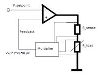
I'm trying to design a circuit that can provide constant power from 6mW to 400mW.
The output of multiplier is V=I*R_sense*I*R_load/k
= P*R_sense/k
The problem lies in the range of setpoint required at low and high power.
Ex:
1. Required P= 6mW, R_sense= 20 Ω. If k= 0.75V, setpoint = 0.16 V.
2. Required P= 400mW, R_sense= 20 Ω. If k= 0.75V, setpoint = 10.67 V.
I feel the setpoint input to the opamp in ex. 1 is too low and we are operating near the noise level in the circuit.
In Ex. 2, the setpoint input is high, close to the maximum output voltage swing of any multiplier IC available.
Fiddling around with k will either increase or decrease either setpoints equally.
P.S.: I've drawn the inverting and non-inverting inputs of opamp incorrectly.
I'm trying to design a circuit that can provide constant power from 6mW to 400mW.

The output of multiplier is V=I*R_sense*I*R_load/k
= P*R_sense/k
The problem lies in the range of setpoint required at low and high power.
Ex:
1. Required P= 6mW, R_sense= 20 Ω. If k= 0.75V, setpoint = 0.16 V.
2. Required P= 400mW, R_sense= 20 Ω. If k= 0.75V, setpoint = 10.67 V.
I feel the setpoint input to the opamp in ex. 1 is too low and we are operating near the noise level in the circuit.
In Ex. 2, the setpoint input is high, close to the maximum output voltage swing of any multiplier IC available.
Fiddling around with k will either increase or decrease either setpoints equally.
P.S.: I've drawn the inverting and non-inverting inputs of opamp incorrectly.
Last edited:

