Continue to Site

Welcome to EDAboard.com

Welcome to our site! EDAboard.com is an international Electronics Discussion Forum focused on EDA software, circuits, schematics, books, theory, papers, asic, pld, 8051, DSP, Network, RF, Analog Design, PCB, Service Manuals... and a whole lot more! To participate you need to register. Registration is free. Click here to register now.

Cut off negative pulse and regulate using zener

Status
Not open for further replies.

neazoi

Advanced Member level 6
Joined
Jan 5, 2008
Messages
4,122
Helped
13
Reputation
26
Reaction score
15
Trophy points
1,318
Location
Greece
Activity points
36,951
Hi,
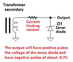
The attached image shows a pulsed transformer secondary.
The transformer can output both positive and negative pulses.
I have used a silicon diode to cut off the negative pulses.

What I need is to cut off the negative pulses, but also regulate the positive pulses using a zenner.
Can both jobs be done using a single zener and how should the zener be connected in the circuit?
 

Attachments

  • nor1.gif
    nor1.gif
    2.4 KB · Views: 64

Your circuit does not "cut off" the negative pulses from the transformer, instead it shorts the transformer with the diode so that both are overloaded. Nothing limits the current.
If the diode is a zener diode then the current though it will be extremely high and destroy it. Again the transformer will be overloaded. Nothing limits the current.
Do it like this:
 

Attachments

  • zener diode.png
    zener diode.png
    6.7 KB · Views: 64
  • Like
Reactions: neazoi

    neazoi

    Points: 2
    Helpful Answer Positive Rating
Your circuit does not "cut off" the negative pulses from the transformer, instead it shorts the transformer with the diode so that both are overloaded. Nothing limits the current.
If the diode is a zener diode then the current though it will be extremely high and destroy it. Again the transformer will be overloaded. Nothing limits the current.
Do it like this:

My application involves logic and the transformer is simply a tiny ring core with 0.1mm wire, that accepts pulses and propagates them to the secondary winding. Working voltages are below 24V and the zener will be used to regulate them to 5V.

Do you think the pulsed current would be too large to destroy the zener?
I would like to avoid the resistor if possible, to increase pulsing speed without flattening down the pulse.
 

Forcing a DC voltage to the transformer output by clipping the output asymmetrically can cause core saturation.

If the circuit serves the intended pupose depends on many details like source impedance, transformer parameters, frequency. Too little information to answer the question.
 

Use the circuit which audioguru shows, but;
-replace the zener with a switching diode 1N4148 oriented the same way. The zener has a wide junction and has too much capacitance.
-feed the output to a NPN transistor (grounded emitter).
-since the transistor will invert the polarity, the transformer's dot side will also have to be reversed.
-you may want to schotky-clamp the transistor to avoid saturation and improve the recovery time.
 

Forcing a DC voltage to the transformer output by clipping the output asymmetrically can cause core saturation.

If the circuit serves the intended pupose depends on many details like source impedance, transformer parameters, frequency. Too little information to answer the question.

I experiment with this and tryying to improve it **broken link removed** Unfortunatelly I do not have more information because I have not seen this technique used for logic in old books, but only for memory circuits.
I thought the zener in place of the silicon diode in order to bring the transformer output voltage level back to the desired value without having to alter the transformer ratio.
 

The current in that very simple circuit is extremely low.

I guess so, it is mainly the voltage that I am interested, or better, the voltage peak of the pulse. So I guess a single zener can be used instead.
 

Flyback operation of a core relies on Np*Ip*Tp of primary current being switched on and released to secondary Ns*Is*Ts for some time Ts determined by RC time constant of the rectifier diode cap load. Thes product terms can be equated if there are no significant core losses or leakage inductance spikes of energy lost.

You only have a voltage limiter zener and none of the above.
 
  • Like
Reactions: neazoi

    neazoi

    Points: 2
    Helpful Answer Positive Rating
Flyback operation of a core relies on Np*Ip*Tp of primary current being switched on and released to secondary Ns*Is*Ts for some time Ts determined by RC time constant of the rectifier diode cap load. Thes product terms can be equated if there are no significant core losses or leakage inductance spikes of energy lost.

You only have a voltage limiter zener and none of the above.

What does it practically mean?
 

Practically all flyback transformers are based on these ratios with pulse transformers storing the energy. The core capacity is in Volt Seconds which is another way to choose a design using input pulse Vin x PW50= Vout x PW50 , for the time of the pulse width at 50%, before the transformer saturates.

In normal transformers it is simply voltage turns ratio with excitation current on primary inductance equal to about 10% of rated current for efficient coupling which determine L from fundamental f.

If your current is AC with a DC flow component then it will reduce the max power transfer before saturation. This is why split winding half bridges or single secondary full bridges are used to commutate current.

your diagram does not meet this requirement.

why not learn to specify your overall in-out requirements? For V,Z,I,P etc
 

why not learn to specify your overall in-out requirements? For V,Z,I,P etc

Thanks for your response.
Indeed I do not know so much about transformers like you seem to. so I have not done any calculations, and all my considerations are based in experimenting.
However, there is no DC component in the design, there are simultaneous short pulse inputs (I am thinking of it as mostly instantaneous AC) that affect the output winding that you see in the schematic.
I do not see why a zener will not work there to cut off the negative pulse and regulate the instantaneous higher voltage pulse, but as I said this is probably because of my lack of knowledge at this point.
I am trying to understand, based on your comments, why this is not going to work. Any help is appreciated.
 

Status
Not open for further replies.

Similar threads

Part and Inventory Search

Welcome to EDABoard.com

Sponsor

Back
Top