Continue to Site

Welcome to EDAboard.com

Welcome to our site! EDAboard.com is an international Electronics Discussion Forum focused on EDA software, circuits, schematics, books, theory, papers, asic, pld, 8051, DSP, Network, RF, Analog Design, PCB, Service Manuals... and a whole lot more! To participate you need to register. Registration is free. Click here to register now.

Replacing zener with gas tube in KWM2-A

neazoi

Advanced Member level 6
Joined
Jan 5, 2008
Messages
4,122
Helped
13
Reputation
26
Reaction score
15
Trophy points
1,318
Location
Greece
Activity points
36,951
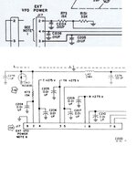
Hi, a Collins KWM2-A I service (1st schematic) does not have stabilized voltage on the VFO and during transmit (where more current is drawn and voltage gets lower) the frequency changes a bit. This is a known problem and fixed on later serial numbers with the zener circuit (2nd schematic).

I wonder if I can use exactly the same peripheral components and just replace the 150v 1W zener with a 0A2 gas regulator tube? (asumming I will find a way to mount it under the chassis).

Thanks
 

Attachments

  • 1.JPG
    1.JPG
    86 KB · Views: 44
Probably, but why?
The Zener is probably the better device for regulation.

Brian.
I thought just to keep the "tube character" of the machine. I do not know if this is a good idea though, cause I was always confused about the series resistors to be used and I do not know the current drawn by the VFO of the transceiver.
 
I'm not sure and I doubt information would be easy to find but I think the dynamic resistance of a gas tube regulator is higher than that of a high voltage Zener diode.

The current through the regulator has to be at least the difference between lowest and highest VFO current and at highest and lowest supply voltage. The idea is that under maximum current draw by the VFO, the Zener passes only a small residual current. If the VFO current drops, a dropper resistor alone would make the voltage rise so the Zener sinks the current instead to keep it constant.

You need to find the current drawn by the VFO first, then subtract the lowest current from the highest to find the difference. It is this difference plus say 1mA added to the VFO current that you use to calculate the resistor value.

Brian.
 

LaTeX Commands Quick-Menu:

Similar threads

Part and Inventory Search

Welcome to EDABoard.com

Sponsor

Back
Top