cupoftea
Advanced Member level 5
Hi,
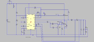
The only way to use any offtheshelf Sync Buck controller is to use a PNP turn off on the low side FET.(as shown in attached LTspice and jpeg)
One needs to add a capacitor to the low side gate so that it doesnt get spuriously turned on by the upper fet turning on. When you have done that , you then must use a PNP turn off, otherwise you just cant turn the lo side gate off quickly enough. You can use a diode to bypass the gate series resistor, but with the logic level fets inevitably needed with these sync buck drivers, the voltage drop of the turn off diode is too high to be able to give a fast and definite turn off. As such, the PNP turn off is needed.
Why do they not show PNP turn off being used in the datasheets?
Another point is that the dead time between top and bottom fet drives is nowhere near long enough. (in any offtheshelf Buck IC) There is no need to have sub 100ns dead time...it just makes it more difficult to use gate delays to avoid shoot through.
Why do they all have such low dead time?