Continue to Site

Welcome to EDAboard.com

Welcome to our site! EDAboard.com is an international Electronics Discussion Forum focused on EDA software, circuits, schematics, books, theory, papers, asic, pld, 8051, DSP, Network, RF, Analog Design, PCB, Service Manuals... and a whole lot more! To participate you need to register. Registration is free. Click here to register now.

Confused about comparator

Status
Not open for further replies.

bittersweetsep

Newbie level 4
Joined
Nov 28, 2012
Messages
7
Helped
0
Reputation
0
Reaction score
0
Trophy points
1,281
Activity points
1,350
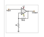
This is an inverting Schimitt trigger circuit
6985279500_1354134490.jpg


The op-amp is comparator here, since it is a positive feedback.

Obviously, the result is when input is higher than ground, then output goes to negative supply, while input is lower than ground, output switches to positive supply.

But my question is since the comparator is one kind of op-amp, then Vin/R1=Vout/R1+Rfb (am I right?) then how to use this equation to explain the above result???

Thanks in advance!!!
 

Attachments

  • 11.jpg
    11.jpg
    9.1 KB · Views: 124

The premise that V(inverting)=V(non-inverting) doesn't apply here. The positive feedback messes that all up.

Look at it this way:
The output is at VCC. Then the voltage at the non-inverting input is VCC(r1/(r1+rfb); call this V(ni). This means that the voltage at the inverting input must be greater than V(n1) in order to get the output to go negative.
Similarly, when the output is at VEE, the voltage at the non-inverting input is: VEE(r1/(r1+rfb).
 
The equation can be used to calculate the comparator input thresholds Vth+ and Vth-. But most of the time, the comparator output voltage is at the rails and doesn't depend on the input voltage.
 
But my question is since the comparator is one kind of op-amp, then Vin/R1=Vout/R1+Rfb (am I right?) then how to use this equation to explain the above result???

No, the comparator is NOT a "kind of op amp". Why not? Because the unit has no fixed operation point within in its linear region. Thus, it works not as a linear amplifier for an input signal and the formula mentioned by you does not apply. Instead, it switches between two possible states forth and back as explained already.
 

Can I put it into this way, only if the negative feedback is employed, then V(inverting)=V(non-inverting)?
 

Can I put it into this way, only if the negative feedback is employed, then V(inverting)=V(non-inverting)?

Yes, that is the practical approach (assuming infinite open-loop gain).
 

in this circuit you know V(+) = V(-) and i(+)=i(-)=0 .

This is 100% wrong.

Op-amps are designed to be used in a closed-loop, negative-feedback configuration. When used in this way V(+) theoretically DOES equal V(-). HOWEVER, when configured with positive feedback that assumption no longer holds.
 
i suggest you do not memorize equations . i think it is better to keep Op-Amp rules in mind and write equations from first .

My I suggest something to you? Keep op-amp rules in mind. That means: Try to UNDERSTAND what`s going on.
 

So what I understand is that normally op-amp what we want works in the linear region, once it operates normally in the saturation region, it becomes a comparator. And only when it operates in the linear region, we can then talk about V(inverting)=V(non-inverting). Right?
 

Right. But also consider, there are comparators and there are opamps, and they ARE different. For many applications an opamp configured as a comparator works fine, but for best performance, use a comparator.
 

So what I understand is that normally op-amp what we want works in the linear region, once it operates normally in the saturation region, it becomes a comparator.

Comparator operation:

1.) An opamp without any external circuitry can be used as a (rather bad) comparator. The output is either positive (supply rail) or negative (supply rail). This depends on the input voltage - if it is either above a certain minimum or below a certain maximum voltage. Both values differ only slightly (µVolt range - dependent on the open-loop gain of the opamp). These considerations neglect the offset voltage.

2.) Another opamp-based comparator circuit uses positive feedback.
Advantages: A certain amount of hysteresis, which improves noise immunity (unwanted switching events) and most important: SPEED of switching.
When the output starts to change its state, this voltage change is fed back to the pos. input and even supports this change of state. Thus, the switching speed is drastically improved.
 
Status
Not open for further replies.

Part and Inventory Search

Welcome to EDABoard.com

Sponsor

Back
Top