Continue to Site

Welcome to EDAboard.com

Welcome to our site! EDAboard.com is an international Electronics Discussion Forum focused on EDA software, circuits, schematics, books, theory, papers, asic, pld, 8051, DSP, Network, RF, Analog Design, PCB, Service Manuals... and a whole lot more! To participate you need to register. Registration is free. Click here to register now.

communication between GSM modem and PIC microcontroller

Status
Not open for further replies.

monika varshney

Newbie level 5
Joined
Apr 12, 2008
Messages
10
Helped
2
Reputation
4
Reaction score
1
Trophy points
1,283
Activity points
1,373
pic modem gsm

i m using a maestro modem which supports both text and PDU mode. and i m interfacing it with PIC 917.

i m able to send AT-commands using hyperterminal with the modem but when i communicate with the microcontroller, i m not able to get the response of AT-commands.
i m sending a string like this:
putc("AT \r\n");

but it is not giving the required response.....it is not giving OK...


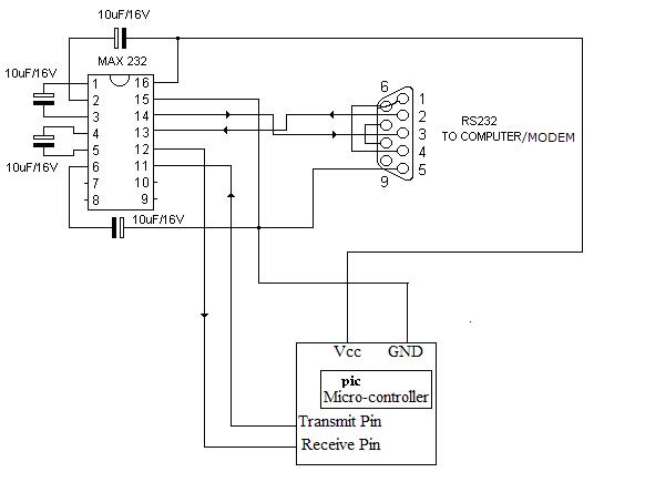
my hardware connections are ----

for DB-9 connector-
pins 1,4,6 are connected.
pins 7 and 8 are connected.
5 is ground.
pin 2 is connected to TX of MAX and pin 3 is connected to RX.

Plz check the connections and guide me accordingly....
 

gsm modem interfacing with microcontroller

Hi,
1. Make your interface connector signals on the board identical to PC's connector and then try.

2. On PC, pin 3 is TX and pin2 is RX, so please match it first.

3. Do you have the pinout details of the modem connector?

Regards,
Laktronics
 

pic gsm modem

i already did that...and i have the pinout of the modem connector..i have done my hardware connection according to that only....
 

gsm module pic microcontroller


this is the schematic of my hardware. Plz check it.

my modem supports 9600 bps. AT this baud rate it is responding with PC.
 
  • Like
Reactions: saipavan56

    V

    Points: 2
    Helpful Answer Positive Rating

    saipavan56

    Points: 2
    Helpful Answer Positive Rating
interfacing gsm modem to microcontroller

Hi,
I suggest you to remove the present connections to pins 4 and 7 of the 9 pin connector. Then:
1. You short pins 4 and 7 of the connector and connect to pin 7 of Max 232 IC .
2. Connect pin 10 of Max 232 to ground.
3. You also connect pin 8 of Max 232 to Vcc through 1K resistor.

Points 1 and 2 ensures that DTR and RTS will be enabled high (10V) if your modem looks for that for communication. This will ensure that the status of PC's connector pins match with your controller connector. Point No.3 is just to ensure that the rx gate is not left open.

In one of the recent discussions in the Forum, it was pointed out that MAX 232 should use all 1uF capacitors only in the place of 10uF caps used to be seen with some of the earlier designs. I am not sure how far the value of these caps will affect, however, it is true that all recent data sheets of Maxim/TI etc. show only 1uF capacitors.

Also, with these changes, you can connect your microcontroller card using a cross connected cable to PC and check if it works with hyper terminal under identical condition of Baud rate etc., which you used while connecting PC to the modem. It will ensure that your micro is working as expected.

Please give us your test results.

Regards,
Laktronics
 

how to interface 8051 with gsm modem

Thanks for your reply...

But i can't understand ..what is the significance of these connections?
Can you please elaborate it more.
 

gsm modem interface with 8051

Hi,
Yes, these connections will make DTR and RTS pins of your card interface connector high. In the cable connecting to your modem, these will be connected respectively to DSR and CTS pins of the modem connector normally. So, in normal RS232 communications if flow control is used in the modem software, it will not send any data to your card unless it sees its DSR and CTS as high, that is why these are required. Since the modem cable worked with PC, I find that your connections are only short of these signals and hence the suggestion. And ofcourse those comments about the capacitor value of MAX 232 also may be noted.

Regards,
Laktronics
 

gsm modem interface with pic

hi,

once check out your schematic. For MAX232 pin13 and pin8 are RS232 inputs.pin3 must be connected to either of it.
 

interface gsm modem pic microcontroller

Hi,
Please do not confuse. Pin 3 of the connector is TX output and the connection is correct. Pins 8 and 13 of MAX 232 are Rx inputs, and one of them is connected to pin 2 (RX) of the nine pin connector and it is right.

Regards,
Laktronics
 

hye.. im new here.. im interested in this topic. can i know the interface of gsm module with PIC16F877A? can anyone help me..?
 

Iam Doing a project using PIC16F877A andGSM modem.How can I read SMS from the MOdem?
 

Thanks for the reply.But I am having the circuit.What I need is to read an SMS from the Modem to the PIC . According to my knowhow its nots easy as sending an SMS using AT commands ..
can any please help me in this ?
My mail id is ratheeshbr@gmail.com
 

ratheeshbr said:
What I need is to read an SMS from the Modem to the PIC . According to my knowhow its nots easy as sending an SMS using AT commands
It's simple - send the command "AT+CMGL". This will return all of the SMS messages in the "preferred storage". Refer to your manual for details on the format of the returned data
 

Hi ratheeshbr,
First, What is your interface to view your sms?
Is it a LCD or anything like it.

The thing is when you interface a microcontroller there is no direct method to view the received data. When you read the modem for sms the data comes to the micro', But you have to reformat it to view it.
 

Hi to all,
can any one help me?
am doing project on GPS Location Alarm.
am using pic16f887 and gm862-gps
and i have to send sms as the alarm.now am working on the gsm to send d sms.
i am able to send the sms using hyperterminal ,both in pdu and text format.
i have done the program to send the releavent AT commands to the modem also.
i can see the result using hyperterminal.it sends the next statemnt only after pressing "ok".but when i send the program to modem its not responding.
am not able to see anything on the hyperterminal.
i am using rs232 interface als.whr TX(pic) to pin 11 and RX(pic) to pin 12.and pin 14(rs 232 ) to 2 of DB9 connector,pin 13 to 3 to DB9,and 15(rs232) and 5(DB9) grounded.now i have connected female DB9 and male DB9 from the same point one is to the modem other to pc.
can u help me why the gsm modem is not responding?
#include <stdio.h>
#include <htc.h>
#include "sci.h"
#include "usart.h"
#include <stdlib.h>


/* A simple demonstration of serial communications which
* incorporates the on-board hardware USART of the Microchip
* PIC16Fxxx series of devices. */

#include <string.h>

void main(void)
{
INTCON=0;

init_comms();
sci_CheckOERR();
printf("AT\r\n");
sci_CheckOERR();
while(1){
if(getch()=='O'){
if(getch()=='K'){
break;
}
}

}
sci_CheckOERR();
printf("AT+CMGF=0\r\n");


while(1)
;
}
void putch(unsigned char byte)
{
/* output one byte */
while(!TXIF) /* set when register is empty */
continue;
TXREG = byte;
}

unsigned char getch() {
/* retrieve one byte */
while(!RCIF) /* set when register is not empty */
continue;
return RCREG;
}


unsigned char
sci_CheckOERR(void)
{
if(OERR) /* re-enable after overrun error */
{
CREN = 0;
CREN = 1;
}
return ;


this is my code.
here i have omitted few lines after at+cmgf=0
now iam able to send dis to hyperterminal
bt problem is modem not responding

can u help me?
mail the reply to anjujohn11@gmail.com
 

when interfacing a microcontroller with a phone you need translator right? because microcontroller operates in 5 v while phone in 3.6 v. my question is. is this same thing when interfacing microcontroller to gsm modem? do we also need translator?
 

same trouble here....
R U sure that the GSM module respon is only OK

coz my code is not working at all, when i connected the pic to gsm

i guess is not only OK, but \nOK\r\n which is \n=0x0A and \r=0x0D

Am I right ??
 

same here i need the code but in micro c
 

Status
Not open for further replies.

Similar threads

Part and Inventory Search

Welcome to EDABoard.com

Sponsor

Back
Top