Continue to Site

Welcome to EDAboard.com

Welcome to our site! EDAboard.com is an international Electronics Discussion Forum focused on EDA software, circuits, schematics, books, theory, papers, asic, pld, 8051, DSP, Network, RF, Analog Design, PCB, Service Manuals... and a whole lot more! To participate you need to register. Registration is free. Click here to register now.

Common Source amplifier with resistive load.

Status
Not open for further replies.

imrankhanPNU

Member level 1
Joined
Feb 21, 2018
Messages
34
Helped
0
Reputation
0
Reaction score
0
Trophy points
6
Activity points
461
Hello,
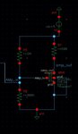
I am new to the amplifier designer. In my demodulator circuit, I have designed CS amplifier to shift the DC level of the modulated signal [attached]. Although I got my desired result, but when I decrease the gain of the amplifier by changing the load resistor then I got an irregular output voltage waveform. I would like to know why this is so?

Specifications: Vdd=5V , Vth= 805mV, Vgs=1.552, Id=548uA , gm=1.06mS, w/L=20
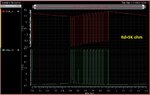
Rd=5K ohm (Av= 5.3 & I get my desired Vout)[attached] .
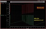
Rd=2K ohm (Av= 2.156 & i get irregular Vout )[attached]
 

Attachments

  • 1.JPG
    1.JPG
    37.3 KB · Views: 225
  • 2.JPG
    2.JPG
    226.1 KB · Views: 210
  • 3.JPG
    3.JPG
    228.7 KB · Views: 194

Your amp is clipping. With the 5K it clips at a lower input level so you don't see that 'curved' part of the response that you do with the 2K. The curved part is when the amp is not fully clipping.
 

Your amp is clipping. With the 5K it clips at a lower input level so you don't see that 'curved' part of the response that you do with the 2K. The curved part is when the amp is not fully clipping.
Thanks for your response. What should I do to reduce/remove clipping from my amp? & What factor cause this chipping?
Looking forward for your suggestion.
 

Wait. You said you "got your desired result". Did you actually NOT get your desired result? Do you NOT want clipping? What IS your desired result?? Your input has that weird DC ramp superimposed on your signal and the amplifier is just amplifying that, along with the signal.
 

You drov the amplifier too much so transistor wants to flow but clipping occurs.
Best method is to adjuts the OP mid point of VDD so VDS should be approximately 2.5 V and Open Circuit Voltage Gain should be considered as\[ A_{v}=-gmR_{L} \]
 

Thanks for your response. The previous result was fine for me, however for my in-depth understand I would like to know how to get the result without clipping? how to get a smooth input signal? Moreover, I have attached a block diagram of my entire system for your reference.
 

Attachments

  • New Microsoft Visio Drawing.jpg
    New Microsoft Visio Drawing.jpg
    12.9 KB · Views: 151

1) To avoid clipping either lower your input signal amplitude or your gain.
2) there is no way anyone can tell you how to get a smooth input signal.YOU’RE generating it, YOU have to figure out how to make it smooth. My guess is that series capacitor is your problem; you’ve got some DC going into it.
 
Status
Not open for further replies.

Part and Inventory Search

Welcome to EDABoard.com

Sponsor

Back
Top