Continue to Site

Welcome to EDAboard.com

Welcome to our site! EDAboard.com is an international Electronics Discussion Forum focused on EDA software, circuits, schematics, books, theory, papers, asic, pld, 8051, DSP, Network, RF, Analog Design, PCB, Service Manuals... and a whole lot more! To participate you need to register. Registration is free. Click here to register now.

CMOS dc -dc convertor design M.E project

Status
Not open for further replies.
Please help me out with this mosfet
Why does it have multiple sources and drains ?

The sources are connected to each other. The drains are connected to each other.

It gives a measure of heatsinking. The heat escapes more easily through several pins than through one.
 

I require a Driver for this MOSFET PSMN1R1-30EL. What specifications should i look for in the driver ? Also can someone suggest me a Driver that i can use to drive a synchronous buck configuration and also which can be hand soldered ?
 

Attachments

  • PSMN1R1-30EL.pdf
    238.1 KB · Views: 82

Your mosfet appears able to do the job.

RON is 1.3 mill-ohm. That is 1/770th of an ohm.

If you send 10A through it, it will develop a differential of .013 V.
That calculates to 130 mW dissipated as heat. This is very good.

If it is not too expensive, it should be suitable.

As for your driver IC...

It must be designed to handle a synchronous buck converter.
It must produce both the high side and low side control signals.

I am not sure how to determine what specs will tell it how control (a) both N-mos or (b) both P-mos, or (c) N-mos upper and P-mos lower, or (d) P-mos upper and N-mos lower.

I don't know what device number to recommend.

There may be an expert here who can give you more information.

will this driver(TPS2833) be suitable to drive this MOSFET ? what effect does it have if the input gets inverted or not in case of the driver attached ?
In case of TPS2833 or TPS2832 will the connections differ ?
 

Attachments

  • slvs195c.pdf
    350.9 KB · Views: 84

I tried simulating a open loop synchronous buck converter using two different types of MOSFET's one is IRF150 and one is PSMN1R1-30EL for same specifications
D=0.1, vin =12, vout=1.2 Fsw=500K, L=900nH,C=500uF
What i noticed is the output voltage settles much faster with lesser oscillations using IRF150 as compared to PSMN1R1-30EL when load step is applied
What may be the reason for this , is it because of the lib file of PSMN1r1-30EL is more detailed as compared to irf150 ?

The damping factor is greater when a higher resistance is inline. Therefore try to determine the 'On' resistance of the two devices.

Try to compare their effect with a plain switch (zero ohms), if the simulation supports such a device.
 

I am trying to sense the inductor current in this circuit. I used the lm741 opamp in differential amplifier configuration.The sense voltage is 50m*12. where 12A is the load current.From my design i should get a output voltage of 3V but i get 2V. And if i connect a resistor to the output of the opamp say 0.25 the voltage drops to mV. How do i sense this inductor current accurately ? I used the opamp in high side current sensing configuration
 

Attachments

  • SCHEMATIC1 _ PAGE1.pdf
    15.3 KB · Views: 98

I am trying to sense the inductor current in this circuit. I used the lm741 opamp in differential amplifier configuration.The sense voltage is 50m*12. where 12A is the load current.From my design i should get a output voltage of 3V but i get 2V. And if i connect a resistor to the output of the opamp say 0.25 the voltage drops to mV.

The 741 has an output impedance of around 75 ohms. This means the output level will be pulled down (distorted) if you attach a low resistance to it.

How do i sense this inductor current accurately ? I used the opamp in high side current sensing configuration

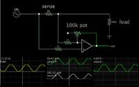
Your schematic is able to work with a few changes.

Your .05 ohm sense resistor will create over 7W of heat, if it has 12A going through it. I believe you can make its ohm value much less, maybe 5 or 10 % of your load impedance.

I find that this setup works (in simulation anyway).


I have made the multiphase buck converter.I tried testing it, but when i connect the input supply to it the supply reduces to some 2.4 from 12V.What is the reason for this ?

- - - Updated - - -

This was done at no load.
 

Status
Not open for further replies.

Similar threads

Part and Inventory Search

Welcome to EDABoard.com

Sponsor

Back
Top