naspek
Member level 1
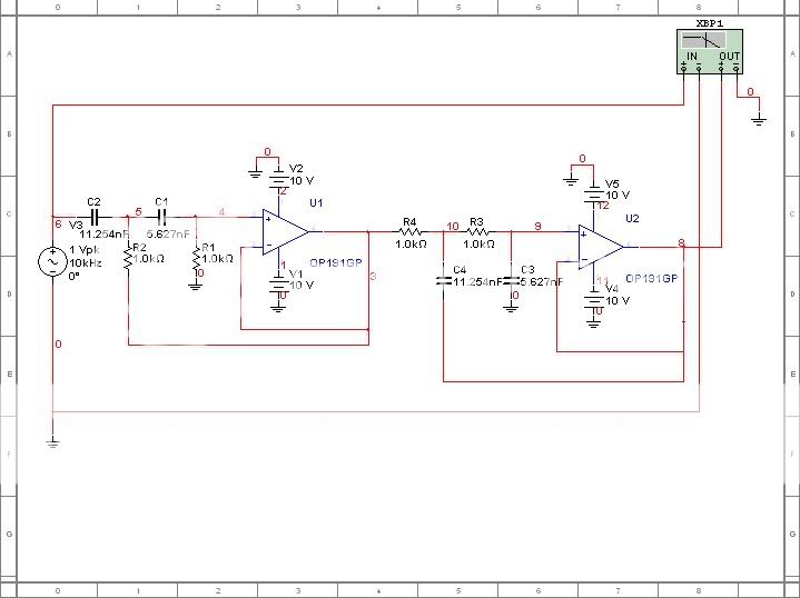
Band pass filter
hey there..
i'm trying to design a bandpass filter with pass band frequency from 10 kHz to 20 kHz and gain = 1
however, my circuit didnt give me the correct graph.. my circuit is correct?
hey there..
i'm trying to design a bandpass filter with pass band frequency from 10 kHz to 20 kHz and gain = 1
however, my circuit didnt give me the correct graph.. my circuit is correct?