D.A.(Tony)Stewart
Advanced Member level 7
- Joined
- Sep 26, 2007
- Messages
- 9,001
- Helped
- 1,823
- Reputation
- 3,645
- Reaction score
- 2,196
- Trophy points
- 1,413
- Location
- Richmond Hill, ON, Canada
- Activity points
- 59,535
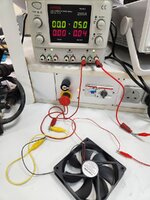
What is the current rating or Pd on fan and load current on DAC?
You can't simply use a FET or a BJT to drive the fan unless you use a very small control range.
It is better to add resistors to control the gain the convert 0 to 10V to fan speed 0 to 100% using negative feedback.
Can you design this or do you need help?
Fan = 3W? DAC can drive 1kohm ?
You can't simply use a FET or a BJT to drive the fan unless you use a very small control range.
It is better to add resistors to control the gain the convert 0 to 10V to fan speed 0 to 100% using negative feedback.
Can you design this or do you need help?
Fan = 3W? DAC can drive 1kohm ?
Last edited: