Continue to Site

Welcome to EDAboard.com

Welcome to our site! EDAboard.com is an international Electronics Discussion Forum focused on EDA software, circuits, schematics, books, theory, papers, asic, pld, 8051, DSP, Network, RF, Analog Design, PCB, Service Manuals... and a whole lot more! To participate you need to register. Registration is free. Click here to register now.

Cable attenuation / input impedance

Status
Not open for further replies.

sh-eda

Member level 1
Joined
Oct 1, 2010
Messages
40
Helped
1
Reputation
2
Reaction score
1
Trophy points
1,288
Activity points
1,735
Hi

Could someone help me with a problem I am looking into regarding a lossy transmission line (again)

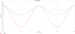
I want to manually calculate what the attenuation and output voltage I should expect for an lossy unmatch cable. I have lossy cable (2).pnglossy cable.pngbeen using Multisim simulate it, (I have attached a screen dump), but I am not getting the same results as Multisim.

I know the formula for attenuation /loss along a cable due to cable resistance.
=Vin*exp(-Rc/(2.Zo)

Where
Rc = cable resistance
Zo = the characteristic impedance.
Vin = cable input Voltage

I think the problem is that I haven't worked out the cable input voltage correctly?
I calculated the input impedance = Zo.[Za + jZo.tan(BL) / (Zo + jZa.tan(BL)) ]
Where
Za = load Resistance
B = Propagation phase constant
L = is the distance

Thanks
 

I know the formula for attenuation /loss along a cable due to cable resistance.
=Vin*exp(-Rc/(2.Zo)
I wonder where the expression comes from and how is it derived.

I calculated the input impedance = Zo.[Za + jZo.tan(BL) / (Zo + jZa.tan(BL)) ]
It's not valid for a lossy line, I presume.

Technically, with the relative low cable resistance in your example, the total attenuation can be estimated with a simple series resistance plus the ripple caused by the mismatch.

Additional comment, the simulation completely misses the frequency dependent attenuation of a real cable, the well-known lack of the simplified SPICE lossy line model.
 

lossy cable1.pngHi

Thanks for answering.
I found the formula in a document. I'll find it again and put it up. Its derived from another formula
Loss = 4.35*Rc/Zo. which is in Np/m. I've seen this often. The multisim model seems to use this.

I have just spotted that drawing is not very clear, it is actually 0.05ohms/m. So around 50ohms over 1km. Which is a bit more significant when compared 200hms.

To be honest I just used the drawing as a simple way for me to work out the principals.
I'm trying to analyse a quite complicated network of loads spaced over 2-3km.

Yes I think you are correct I have just read that the formula Zo.[Za + jZo.tan(BL) / (Zo + jZa.tan(BL)) ] is only for lossless cables.

If these formulas are not correct, could you please show me how to work out the circuit (the loss, input impedance, input and output voltages etc)?

Thanks
 
Last edited:

For a lossy RLCG transmission line the coefficient β has to be substituted with the complex propagation constant γ. This is defined as:

γ=√[(R+jωL)•(G+jωC)]

where R is the resistance, L the inductance, G the conductance and C the capacitance all of them per unit length.

From this we can calculate α=real(γ) and β=imag(γ). α is in neper/m and β in rad/m.
α is responsible for the attenuation and β for the phase delay. Please note that γ depends from the frequency.

The attenuation, in case of matched cable, is exp(α•x) where x is the distance from the generator, that is the length of the cable if you want to know the input/output attenuation.

However if ωL >> R and ωC >> G can be proven that α≈R/(2•Zo)+G•Zo/2
If G is negligible we have the formula you indicated .

Zo=√[(R+jωL)/(G+jωC)]

Usually L and C can be considered as constant over frequency, while usually G increases linearly with frequency and R increases following the square root of the frequency.

In case of unmatched load you'll have also to account for the losses due to this.

By the way the conversion from neper to dB is:

dB=neper•8.686
 

Hi
Thanks for answering
I managed to derive and calculate the propagation values, α and β. I know what the resistance and inductance will be due to skin and proximity effect etc.
So, if the cable is not matched how do you work out the input impedance for a lossy line, for a particular frequency? I'm stuck on this.
I need this so I can work the input voltage to the cable, after the source impedance and so work out the output voltage at a given length.
 

am I missing something? You have 1000 meters of a 0.05 ohm characteristic impedance cable? I seriously doubt the characteristic impedance can physically be that low...I do not think they make flexible dielectric materials whose er=1000 or so to achieve that in a cable
 

am I missing something? You have 1000 meters of a 0.05 ohm characteristic impedance cable? I seriously doubt the characteristic impedance can physically be that low...I do not think they make flexible dielectric materials whose er=1000 or so to achieve that in a cable

I've understood 0.05 ohm/m are the ohmic losses, not the characteristic impedance of the cable.
 

still does not look right, R = 0.05 nF/m ?? Units are wrong.

I do see now that 100 ohms appears to be the characteristic impedance, my bad
 

still does not look right, R = 0.05 nF/m ?? Units are wrong.

Yes you are right. In the second picture R is correct, but L in uF/m. However I think the picture is only for illustration purposes, while the question is rather theoretical.
 

Yes cable inductance L in uF/m is a typo error. Should be 1uH/m, so 1mH over 1km.
and yes characteristic impedance is 100ohms.
Thanks
 

About the input impedance, if your line is terminated on ZL, you can use the formula you indicated substituting β with γ and tan with tanh, that is:

Zin = Zo.[ZL + jZo.tanh(γL) / (Zo + jZL.tanh(γL)) ]

The same for Zout, where ZL will be now the generator impedance.

Then you will have a total attenuation due to the transmission line itself calculated from the coefficient "α" and depending from the frequency + (if you work in dB) the input mismatch loss + the output mismatch loss.
The voltages can be calculated taking into account forward and reflected wave; they will sum with the phase given by "β" (then depending from the length of the cable).
In general if both input and output are mismatched a theoretically infinite "ping-pong" of the wave from input to output will took place and should be taken into account in the calculation. However since the wave will be increasingly attenuated each travel, one way only should be enough to have sufficiently accurate results.
 

A practical solution could be to use the results of the circuit simulator, provided you put in realistic R values (skin effect corrected) for the frequency of interest.

Generally the input impedance can be calculated based on s-parameters and two-pole cascading formulas, but it's a bit involved for a lossy line.
 

Hi
Thanks
Yes I have been using simulator to analyse the transmission line I am working on. The real circuit is quite alot more complicated, I prefer to understand what is going on before trusting it.
I think at the frequency I am looking at the skin and proximity effect multiplies the cable resistance by about 3.5.
I've been through most of the calculations now for Zin, and the propagation constants and also response to a step input which help me understand what was going on.
I think I've got it now. What was confusing me was the variation of the output voltage (with frequency) at the load, when the input source impedance did not match the cable characteristic impedance. I found a document that I have attached that helped.

As mentioned, the signal ping pongs back and forth and the reflections from the source impedance also adds to or subtracts from the input signal, depending upon the reflective coefficient of the source. The reflected signal in each direction gets attenuated as well.
I found a formula which determines the final output voltage when the ping ponging has finished (no loss).
VL = V1 ((1 + RhoL) / (1 - RhoS. RhoL))

Where VL is the voltage across the Load resistor,

V1 is the initial input voltage = Vs . (Zo / (Zo + Rs). (Rs is the source impedance, Zo is the characteristic impedance).
RhoS = Source reflective coefficient
RhoL = Load reflective coefficient

I think at certain frequency the reflections are effectively negative rather than positive. So the formula changes.
VL = V1 ((1 + RhoL) / (1 + RhoS. RhoL))


Thanks
 

Attachments

  • chapt13.pdf
    2 MB · Views: 46
  • Untitled.png
    Untitled.png
    38.7 KB · Views: 44

As mentioned, the signal ping pongs back and forth and the reflections from the source impedance also adds to or subtracts from the input signal, depending upon the reflective coefficient of the source. The reflected signal in each direction gets attenuated as well.
I found a formula which determines the final output voltage when the ping ponging has finished (no loss).
VL = V1 ((1 + RhoL) / (1 - RhoS. RhoL))
I don't see a definition of RhoS and RhoL in your calculation, in so far I'm not sure what the expression means.

We can't say that the "ping ponging" ever finishes with a stationary input voltage. Instead we can calculate the transformed load impedance at the cable input (or the transformed output impedance at the cable end) using the formula in post #11, which will be complex in the general case. Then calculate the actual cable input (or output voltage) for the specific frequency.

If I understand right, you have finally realized that the simulation result is basically correct and can be trusted.
 

Hi
Sorry for not being clear, (I used the wrong symbol name should be 'Γ')
RhoL was the load or teminating reflection coefficient.

= (RL - Zo) / (RL +Zo)

RhoS was the source reflection coefficient.

= (Rs - Zo) / (Rs +Zo)

I'm happy it works for a single lossy line. I'm looking at it for a more complicated circuit at the moment, as in the image I've attached. (I'm just keeping it simple by using 1km)
 

Attachments

  • Untitled.png
    Untitled.png
    40.4 KB · Views: 54

Status
Not open for further replies.

Part and Inventory Search

Welcome to EDABoard.com

Sponsor

Back
Top