Vermes
Advanced Member level 4
Assumptions
- the current speed
- the current frequency of the pedaling rate
- trip distance
- travel time
- the average travel speed
- maximum travel speed
- backlight
- velocity relative to time graph
- speed relative to distance graph
- the change in circumference of a wheel
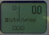
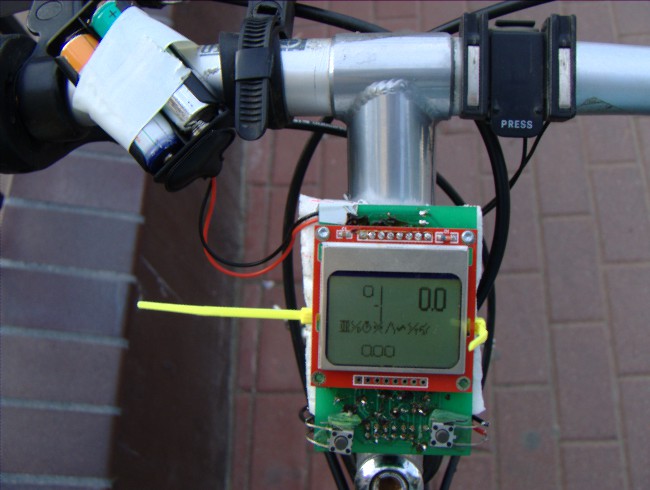
The crank rotation is seen on the left (along with scale, which shows 0 and optimum). On the right side the current speed is shown, list of modules and at the bottom – the current module (in this case, the distance).
The whole device operates on two wire sensors with reeds, three or two buttons and two AA batteries 1,2V.
The buttons are used mainly for scrolling and selecting the modules, but generally it depends on the module – for example, pressing the selection of the distance module clears the distance, pressing the selection of the circumference of a wheel allows to change it.
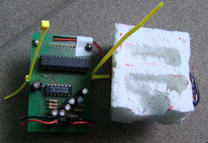
Equipment
- Atmega8
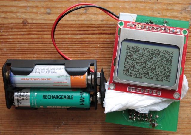
- Nokia 5110 display
- parity generator
- buttons
- sensors based on reeds
Software
Project was written in C, with six lines assembly. The most is in C89, but sometimes there are GNU99 and C99 amplifications. So it may be compiled with GCC.
The software is divided in core, sensors and modules. The sensors collect data. The modules display data, they have a simple construction and are easy to be written. The core links all those.
The code itself is based on both the interrupts and the main loop. Interrupts are responsible for collecting and storing data. The main loop is responsible for displaying data.
Assembly
The screen is soldered permanently and the sensors use BLS-02 ends. It was attached to the bicycle with help of Styrofoam and special snaps.
The photo of the meter with batteries.
Link to original thread – Licznik rowerowy na bazie AVR