Tahmid
Advanced Member level 6
- Joined
- Jun 17, 2008
- Messages
- 4,756
- Helped
- 1,798
- Reputation
- 3,588
- Reaction score
- 1,656
- Trophy points
- 1,413
- Location
- Berkeley, California
- Activity points
- 30,584
Follow along with the video below to see how to install our site as a web app on your home screen.
Note: This feature may not be available in some browsers.
Hi,
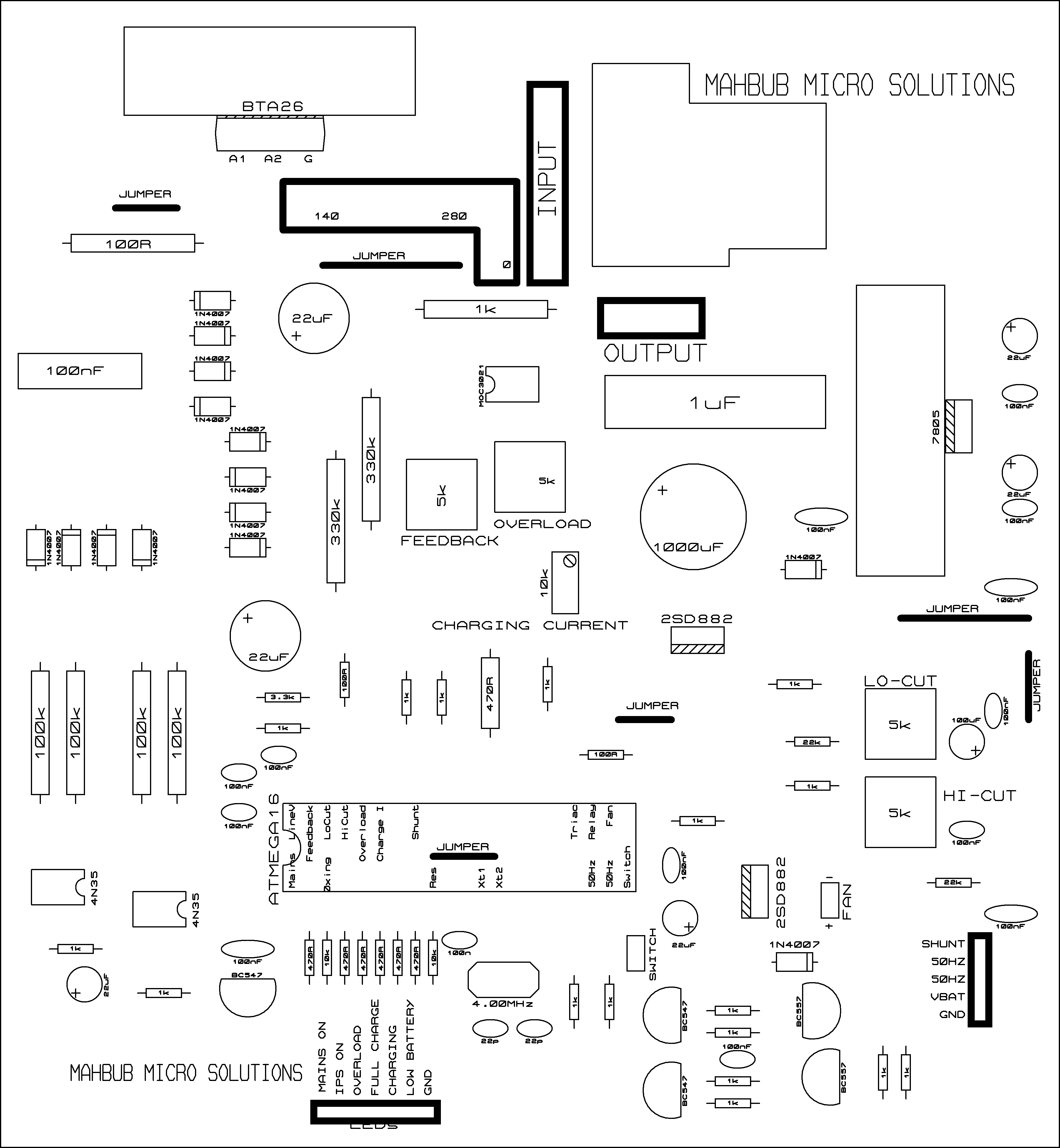
They aren't SMD. I designed in ARES (PROTEUS) and when exported to image file, they become like that. Here's the original file.
Dear Tahmid,
i am also impressed so far for all your contribution to this forum, i hope u post also PCB & CKT , where is the software for the atmega?
Hi Tahmid,
Thanks alot for this write up, it is well explained. i will read it very well before i ask more question but first -:
1. must the amplitude of our sine wave be always equal to our switching period? if not can any amplitude of our choice
be use? if yes then what will inform our choice of a particular figure?
2. what is the relationship between this sine wave table and out reference value within the contex of sine wave inverter
that require vref?
regards
Hi Tahmid what is size of your inverter,s pcb.
1------>In a typical sine wave inverter design, must the peak amplitude be equal to the swithing period?
if not, what value of peak amplitude must we use for the sine table and what must informe our choice of that value?
2------>the switching pulse has a maximum output of 5V in microcontroller implementation and the modulation ratio
ma=peak sine/ peak carrier, in the example use in your write-up, what is our amplitude modulation ratio?
and how do we generate a signal with a particular modulation ratio e.g 0.7 modulation ratio?
I will take a look at this. In the meantime, make sure you have .NET 3 installed. You can download it again and see if by any chance, you're missing it. Other than that, I don't see why this problem arises.note: when run your software sine wave misc.exe from the zip file i still get the same error result, i try to execute the sine wave misc manif
and got the eror messagecannot continue. the application is improperly formated.
6" X 6.5"
Tahmid.
---------- Post added at 12:41 ---------- Previous post was at 12:35 ----------
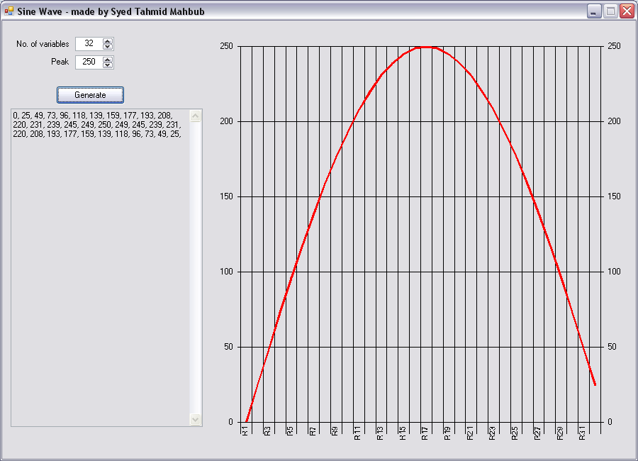
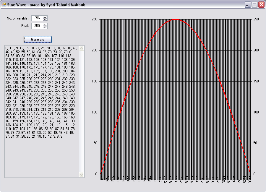
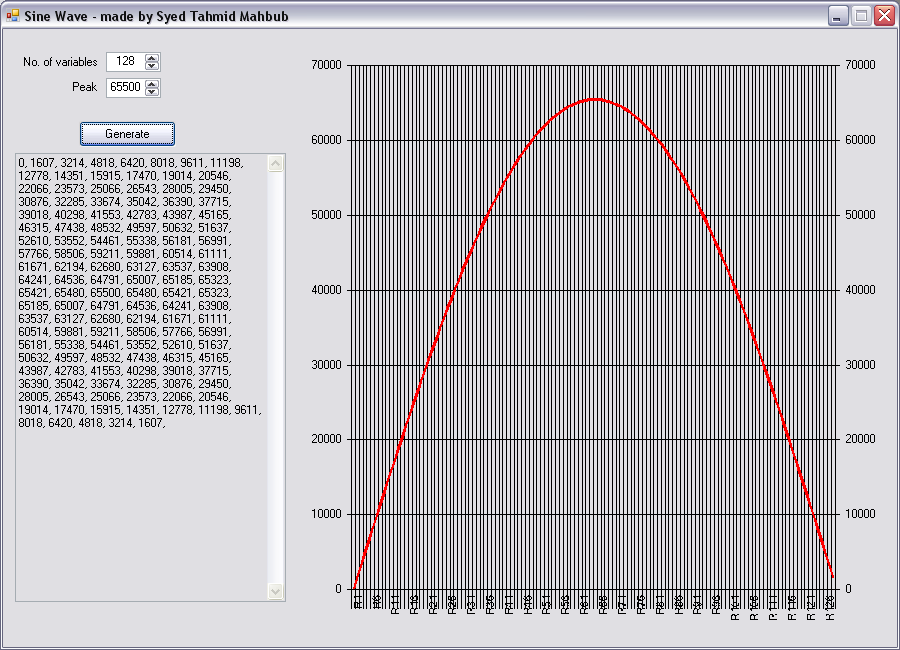
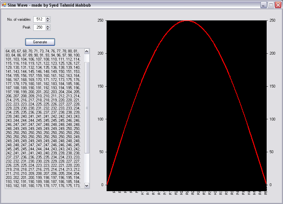
The peak amplitude and rest values also determine the amplitude of the wave. When it equals the switching period, you'll get the maximum voltage (100% duty cycle) available for that input voltage. You can reduce it. You'll get a sine wave, but you'll have a lower voltage. You can adjust it for feedback if necessary.
Can you explain what you mean by amplitude modulation here?
If you mean, to adjust the amplitude of the wave, then like I've said above, you'll have to adjust the peak of the sine table and all the other accompanying values by the same ratio.
Hope this helps.
Tahmid.