Welcome to our site! EDAboard.com is an international Electronics Discussion Forum focused on EDA software, circuits, schematics, books, theory, papers, asic, pld, 8051, DSP, Network, RF, Analog Design, PCB, Service Manuals... and a whole lot more! To participate you need to register. Registration is free. Click here to register now.
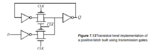
This circuit consists of two transmission gates.The top transmission gate is present so that the previous data can be read out in the absence of a positive clock i.e.(when Φ=0) .Consider if no inverters were to be present,whenever the transmission gate is OFF,its output is Z(High Impedence).This causes the previous state value to be read as Z(High Impedence).In order to avoid this , two inverters are present. Anyways a minimum of two inverters are required.The inverter is present before the transmission gate so as to get both the outputs Q and Q'.Hope this helps.
This site uses cookies to help personalise content, tailor your experience and to keep you logged in if you register.
By continuing to use this site, you are consenting to our use of cookies.