Continue to Site

Welcome to EDAboard.com

Welcome to our site! EDAboard.com is an international Electronics Discussion Forum focused on EDA software, circuits, schematics, books, theory, papers, asic, pld, 8051, DSP, Network, RF, Analog Design, PCB, Service Manuals... and a whole lot more! To participate you need to register. Registration is free. Click here to register now.

Accurate CLK vs. PLL

Status
Not open for further replies.

moottii

Full Member level 2
Joined
Feb 22, 2012
Messages
120
Helped
13
Reputation
26
Reaction score
13
Trophy points
1,298
Activity points
1,962
Hello friends

I need to generate an 1 MHz and 100 KHz clock in ALTERA DE2-115 FPGA board. The clock must be accurate and the rising edge of both must be matched.
The board has a 50 MHz clock. I wanna ask you guys, can I use this clock to generate these clocks with a good accuracy?
And also I wanna know what is "PLL" using in FPGA boards?

Thanks in advance
 

Details about Cyclone II FPGA PLL are described in the device handbook, sownloadable from Altera. Minimum PLL output frequency of Cyclone II family is however 10 MHz, so PLL isn't an option to generate the said frequencies. You need to use synchronous counters as frequency dividers which implies a certain delay against system clock. The question is at which place you want matching of clock edges and up to which tolerance? If limits are low, you may want to generate a clock with negative delay by PLL and divide it for the 100 kHz and 1 MHz clock.
 
  • Like
Reactions: tpetar

    tpetar

    Points: 2
    Helpful Answer Positive Rating
Thank you dear FvM.
But DE2-115 is Cyclone IV
These clocks sample serial data synchronously. So they must be accurate. How much? I don't know... But surely the must be as accurate as possible.
(In fact the clock is used for MDC (Management Data clock in Physical layer of OSI model) to sample the MDIO if you know what MDC and MDIO are)
 

DE2-115 is Cyclone IV, fine than the is able to generate the intended frequencies.

But surely the must be as accurate as possible.
(In fact the clock is used for MDC (Management Data clock in Physical layer of OSI model) to sample the MDIO if you know what MDC and MDIO are)
I believe to know a it about it. I fact, there isn't any strict timing requirement for MDC, except for minimum clock cycle and a rough relation of MDIO and MDC. MDC can be easily generated in FPGA logic together with sending/receiving MDIO. It's almost similar to a SPI interface, with bidirectional data line and no slave select.

I guess, you are chasing a pseudo-problem.
 
  • Like
Reactions: tpetar

    tpetar

    Points: 2
    Helpful Answer Positive Rating
I need to generate an 1 MHz and 100 KHz clock in ALTERA DE2-115 FPGA board. The clock must be accurate and the rising edge of both must be matched.
The board has a 50 MHz clock.

1 MHz = 50 MHz / (2 x 25) (FSM with 25 states for each 50MHz clk transition)
100 kHz = 1 MHz / (2 x 5) (FSM with 5 states for each 1MHz clk transition)

Would that work ? I mean I see it hard to get any more accurate than dividing the clocks down.

/R
 

Would that work ? I mean I see it hard to get any more accurate than dividing the clocks down.
A PLL would be able to generate the clock with zero, or an arbitrary delay relative to system clock. Cylone IV PLL e.g. can do it. But it's apparently not required for the discussed problem.
 

A PLL would be able to generate the clock with zero, or an arbitrary delay relative to system clock. Cylone IV PLL e.g. can do it.
Ok, cool, good to know (being an FPGA newbie, but having done CPLDs and lot of electronics designs) :)
 

A PLL would be able to generate the clock with zero, or an arbitrary delay relative to system clock. Cylone IV PLL e.g. can do it. But it's apparently not required for the discussed problem.

So... you mean there is no need to use PLL.
Is it possible to use a counter, which pulses each 50 clocks => 1 Mhz = 50 MHz/50
and the same for the other one?
i guess since they have different delay, It cannot...
 

So... you mean there is no need to use PLL.
Is it possible to use a counter, which pulses each 50 clocks => 1 Mhz = 50 MHz/50
and the same for the other one?
i guess since they have different delay, It cannot...
If both 1MHz & 100kHz are driven from an edge of the 50MHz clk, then I'd assume they'd be very well matched (order of sub-nanoseconds?).
 

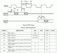
Something similar to a counter. As a first point, you should review the SMI timing specification of your network chip. Usually MDIO is set on the falling edge of MDC and sampled on the rising edge. The signal timing can be easily generated in a state machine.

See below the SMI timing specification of SMSC8720A, a recent 100 MBit ethernet PHY.

 
Yes...
I have read the datasheet of my PHY before.
I wasn't sure about it. Now I can make it.
Thank you dear FvM and robiwan
 

Status
Not open for further replies.

Similar threads

Part and Inventory Search

Welcome to EDABoard.com

Sponsor

Back
Top