Continue to Site

Welcome to EDAboard.com

Welcome to our site! EDAboard.com is an international Electronics Discussion Forum focused on EDA software, circuits, schematics, books, theory, papers, asic, pld, 8051, DSP, Network, RF, Analog Design, PCB, Service Manuals... and a whole lot more! To participate you need to register. Registration is free. Click here to register now.

[SOLVED] 89s52 interfacing with 74HC595 shift register program

Status
Not open for further replies.
You have to use shift as I explained in the previous post, in order to show a single character you send seven different bytes (the content of array a) so if you try to do what you say you will only shift the last byte that was send to the 595 which is pointless.
You have to shift all the bytes contained in the array.

Alex
 
void main()
{
P2 = 0x00;
P3 = 0x00;

while (1) {
delay(1);
for (l = 0; l < 20; l++) {
for (i = 0; i < 8; i++) {
P2 = (1 << i);
delay(1);
sendserial(~a);
//delay(1);
}
}

temp = a[0];
for (j = 0; j < k; j++) {
a[j] = a[j + 1];
if (j == k - 1) {

a[j] = temp;
}
}

}
}

sir you said that , like the above program ?
 
Last edited:

What does each byte in the array represent, a column or a row?

i meant something like


Code C - [expand]
1
2
3
4
5
6
7
8
for (i = 0; i < 8; i++) {
    for (i = 0; i < 8; i++) {
        P2 = (1 << i);
        delay(1);
        sendserial(~(a[i]<<i2));  // or sendserial(~(a[i]>>i2)); for the opposite direction
    }
    // you probably need some delay here
}


but I have no idea if it will scroll in the horizontal or the vertical axis

As a note , your array A has 7 bytes A[0] to A[6] so why do you use 8 loops (A[0] to A[7]), A[7] is not defined

Alex
 
sendserial(~(a<<i2));
what is <<i2;
what will happen <<i2

i got error as follows when it run

Build target 'Target 1'
assembling STARTUP.A51...
compiling g.c...
G.C(24): error C202: 'i2': undefined identifier
Target not created
 

Yes sorry, that was my mistake, I forgot to change the variable of the first loop


Code C - [expand]
1
2
3
4
5
6
7
8
for (i2 = 0; i2 < 8; i2++) {
    for (i = 0; i < 8; i++) {
        P2 = (1 << i);
        delay(1);
        sendserial(~(a[i]<<i2));  // or sendserial(~(a[i]>>i2)); for the opposite direction
    }
    // you probably need some delay here
}


Also declare i2 as you do with i

<<i2 will shift the data i2 positions
 
But it shifts horizontally .

i rotates the array value after displaying as follows .


unsigned char temp;
unsigned char a[] = { 0x00, 0x00, 0x70, 0x88, 0x80, 0x70, 0x08, 0x88, 0x70,
0x00, 0x06, 0x05, 0x01, 0xFE, 0x00, 0x00, 0x00, 0x00,
0x00, 0xF0, 0x08, 0x48, 0xAB, 0xF3, 0x01, 0xFF, 0x00,
0x00, 0xC0, 0x20, 0xC0, 0x80, 0xD0, 0xA9, 0x92, 0xE1
};

unsigned int i2, l, i, j, k = 36;
void main()
{
P2 = 0x00;
P3 = 0x00;

while (1) {

for (l = 0; l < k; l++) {
for (i = 0; i < 8; i++) {
P2 = (1 << i);
delay(1);
sendserial(~a[i]);
delay(75);
}
temp = a[0];
for (j = 0; j < k; j++) {
a[j] = a[j + 1];
if (j == k - 1) {
a[j] = temp;
}
}

}

}
}

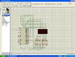
But sir here it clearly moves in one LED matrix 8x8 .
when i connect another matrix with 74HC595 ,the the same letter or character shows in the two matrix
twice scrolling
I want to scroll a letter from one matrix pass and come to the next and so on .
what can i do
please see the picture
gk.JPG
 
Last edited:

This should work to scroll in one display


Code C - [expand]
1
2
3
4
5
6
7
8
for (l = 0; l <29 ; l++) {
            for (i = 0; i < 8; i++) {
                P2 = (1 << i);
                delay(1);
                sendserial(~a[i+l]);
                delay(75);
            }
        }


for two displays you have to change accordingly, send the 16 bits to the 595 and then toggle the STCP to output the data.

In your array you are using 9 bytes for each character, why is that?
I would expect 8 bytes since there are 8 lines.

Alex
 
It may be OT.
I use 74HC595 to build static mode 1-line moving message sign.
I use one 74HC595 IC for each 8-pixel column.
And since I also use AT89S8252 (AT89S8253 or SST89E58RD), I take advantage of its simple SPI serial interface via the two pins:

P1.7 for clock
P1.5 for serial data

For the common latch and output enable lines, I send their signal via 2 other pins.

Unfortunately, all my 8051 firmware codes are written in assembly.

So if the sign has 64 columns to display English message only (one direction), I send one byte for each new frame then strobe all cascaded 74HC595 to update their outputs. This lets the displayed message be shifted by one column at a time (typical speed 32 cols/sec). In case the message should be moved in the opposite direction, all 64 bytes should be sent to refresh each frame (also with a typical speed 32 frames/sec). Text speed could be varied as convenient.

Kerim

PS: I mean by static mode that the display LEDs are frozen (keep their state as on or off) if the controlled signals (mainly the latch signal) stop or are removed. This is not the case for signs using a scan mode LED driver.
 

I designed a lot LED matrix display software,and now i use like MBI5026... 16bit led driver,maybe you can designed a hardware to test it.sorry my poor english.
 

thanks sir but what is the logic to sent 16 bit to the two 74hc595
how can i sent 2 array value to the 74hc595 ?
 

You have to send in the 595 2 bytes at a time

A[0] and A[8]
A[1] and A[9]
A[2] and A[10]
....

to use the 595 with 16 bits you have to send all 16 bits the same way as you send the 8 bits now and at the end (after the 16 bits) toggle STCP

so instead of the way for 8 bits:

Give to DS the value of D7
toggle SHCP (to 1 and back to 0)
Give to DS the value of D6
toggle SHCP (to 1 and back to 0)
....
Give to DS the value of D0
toggle SHCP (to 1 and back to 0)
toggle STCP (to 1 and back to 0) to see the data in the output


you have to use this for 16 bits

Give to DS the value of D15
toggle SHCP (to 1 and back to 0)
Give to DS the value of D14
toggle SHCP (to 1 and back to 0)
....
Give to DS the value of D0
toggle SHCP (to 1 and back to 0)
toggle STCP (to 1 and back to 0) to see the data in the output


Alex
 
i got the idea but ,
may i get some example sir ?
 

I don't have any example since I haven't used such displays so give it a try and post your code here if you have problems with it.
You were able to write the code for 8 bit so I'm sure you can write it for 16bit too.

Alex
 
ok i will try sir

---------- Post added at 12:33 ---------- Previous post was at 11:40 ----------

great sir now ok thanks again
 

Actually I thought of a small modification in your code that should be able to work fine for two or more display, it is not necessarily the best way.

Code:
void sendserial(unsigned char gireesh)
{
    unsigned char gk;
    P3_0 = 0;
    //P3_1 = 0;  [COLOR="#FF0000"]this has been moved to the main[/COLOR]

    for (gk = 0x80; gk; gk >>= 1) {
        if (gireesh & gk) {
            P3_2 = 1; // Data 1
        } else {
            P3_2 = 0; // Data 0
        }
        
        P3_0 = 1;// shcp    [COLOR="#FF0000"]the order of these two lines was wrong in the previous code, you need 0->1->0 for the clock[/COLOR]
	P3_0 = 0; //shcp
    }
    //P3_1 = 1; //stcp  [COLOR="#FF0000"]this has been moved to the main[/COLOR]


}

------------------------------------
[COLOR="#FF0000"]this following is from the main[/COLOR]

for (l = 0; l <21 ; l++) {
    for (i = 0; i < 8; i++) {
        P2 = (1 << i);
        delay(1);
		
        P3_1 = 0; //stcp   [COLOR="#FF0000"]I have moved this here from sendserial[/COLOR]
		
		sendserial(~a[i+l+8]);   [COLOR="#FF0000"]send 8 bits for display2[/COLOR]
		sendserial(~a[i+l]);  [COLOR="#FF0000"]send 8 bits for display1[/COLOR]
		
		P3_1 = 1; //stcp  [COLOR="#FF0000"]I have moved this here from sendserial, toggles after all 16 bits have been send[/COLOR]
		
        delay(75);
    }
}

Alex
 
getting flickering how can i avoid the flickering ?
any calculation for the above program
 

You mean in proteus?
It is because the simulation is not in real time (cause by high cpu load) so you see the flickering because everything works slower than reality.
Maybe try with lower delays but I don't think it will change anything.
 

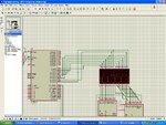
Not in Proteus i made 8X16 matrix ,
but i haven't use ULN driver .because i want to connect a led driver through P2 port of controller ,here coming positive pulse and connected to
LED's positive terminals. (so i cant use ULN2803 because the positive pulse inverted isnt it ?(can i use any other ?))
please see the picture
proteus.JPG
 

Status
Not open for further replies.

Similar threads

Part and Inventory Search

Welcome to EDABoard.com

Sponsor

Back
Top