Continue to Site

Welcome to EDAboard.com

Welcome to our site! EDAboard.com is an international Electronics Discussion Forum focused on EDA software, circuits, schematics, books, theory, papers, asic, pld, 8051, DSP, Network, RF, Analog Design, PCB, Service Manuals... and a whole lot more! To participate you need to register. Registration is free. Click here to register now.

Help-How to boost +7.4v to +75v DC? (for electroluminescent wire driver)

Status
Not open for further replies.

AleXYZ

Junior Member level 3
Joined
May 12, 2010
Messages
29
Helped
4
Reputation
8
Reaction score
4
Trophy points
1,283
Location
USA
Activity points
1,697
I am trying to create a portable EL-wire driver that can handle a wide range of wire lengths, up to 100 feet if possible. EL-wire takes roughly 50mW per foot to glow brightly. I've been designing buck converters successfully for about 2 years now, so I thought this would be easy. But....

I am having a problem boosting 7.4 volts to the needed 75 volts. When I do get 75 volts, my bench experiments yield virtually no usable current.

Here are the details:
* Unit will be battery powered, from 2 LiIon cells for a working voltage range of 6-8.4v.
* I am using a dual H-Bridge (already prototyped and tested) to convert +75v to 120 VAC at 400-1500 Hz.
* Unit must be pretty small, in other words I'd like to avoid big heavy transformers if at all possible
* +75v rail must be actively regulated (see circuit)
* Max. output from inverter needed is 75v @ 0.1A which should be enough to power about 100 ft of El-wire
* Want to make the inverter from SCRATCH, not buy an off-the-shelf unit
* I will probably use a newer model PIC microcontroller to handle any PWM timing requirements (the H-Bridge needs it anyway)


Here are the three topologies I've considered:
* Switched-capacitor. Problem is, I haven't found any devices that can go above 30v. Also, their output wattage is somewhat low.
* Flyback transformer. May be my best bet, but haven't found a transformer small enough for the job.
* Boost converter. This is the route I'd prefer to take. BUT. In my bench experiments I have not been successful (see below) and although I can achieve 75v, I cannot get more than a milliamp or two.


My Boost Converter Experiments:
For the math and circuits, I used these two websites to calculate the inductor and frequency:
Make a simple boost converter
Coilcraft - RF chip inductor, power inductor, power magnetics, and other inductors
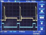
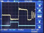
Since I have a lot of 100uH inductors left over from my buck converter projects, I decided to experiment with those. I chose a frequency of around 15 kHz which yielded a duty cycle around 90%. So far so good. The attached circuit is sitting on my desk right now. I am using an Agilent U8002A power supply instead of batteries. I have a frequency generator set at about a 85% duty cycle and a full range of frequencies to play with.

The circuit as shown gives me only about +30-35 volts, and I have to tune the frequency to find it. The best output occurs at around 4 kHz. This morning, I replaced the Darlington transistor arrangement with a power MOSFET and got better results. It kicks up to +60 volts when I tune it to 2.5 kHz, but still no usable current. As soon as I load it with the H-Bridges, the voltage collapses to about 12 volts... and that's with only 1 foot of El-wire attached!

By pushing the limits on the U8002A to 7.25v and 0.4A, the output will hit about +50 volts and the El-wire just barely begins to glow. But that means I'm pushing almost 3 watts of current into the boost converter and getting less than 50 milliwatts out. The components are all rated at 100v or greater. The MOSFET gets a little warm, though not much. The inductor and diode stay cold. Where is all that energy going?


What To Do?
I am not committed to using a boost topology for this project. If anyone has a suggestion how to get the needed voltage with decent current, I'm all ears. Or if you have an idea how to fix my buck design to get higher current yield, I'd really like to know.


75 volts at 100 milliamps? Anyone?
 

Attachments

  • boost_converter.gif
    boost_converter.gif
    17.1 KB · Views: 237

Here are the three topologies I've considered:
* Switched-capacitor. Problem is, I haven't found any devices that can go above 30v. Also, their output wattage is somewhat low.
* Flyback transformer. May be my best bet, but haven't found a transformer small enough for the job.
* Boost converter. This is the route I'd prefer to take. BUT. In my bench experiments I have not been successful (see below) and although I can achieve 75v, I cannot get more than a milliamp or two.
Switched capacitor won't work. Boost can work, but will be inefficient due to the high duty cycle necessary. A transformer based converter like flyback or forward is the best choice. The downside is that the transformer will have many specifications, and finding an off-the-shelf part that meets them is often difficult, or impossible. That's why I wind my own...

If size is a concern, you want to increase your frequency. Hundreds of KHz, if possible. The selection of your FET and diode will be important too. Get fast parts with appropriate voltage ratings (at least 100V, probably more). Also you'll want a proper gate driver IC to drive the FET. Are you really trying to drive your FET with a logic gate through a big resistor? Your switching times are probably very slow, which might be what kills your output power. The output voltage of the gate might not even be enough to saturate the FET. You should be seeing rise/fall times on the drain of no more than a few hundred nanoseconds.

Also, you'll want a better feedback loop if you actually want to regulate the output.
 
  • Like
Reactions: AleXYZ

    AleXYZ

    Points: 2
    Helpful Answer Positive Rating
Have a look at,

https://www.edaboard.com/threads/199540/#post839730

For a basic boost converter using a UC3843. In your case since you wish to operate from 'low voltage' batteries you would have to use one of the BiCMOS variants.. They have lower Under Voltage Lock Out, UVLO, specifications.

UCC3801
UCC3802
UCC3803
UCC3804
UCC3805

https://www.ti.com/lit/gpn/ucc3803


I would suggest either the 3803 or 3805 given that they will start up from 4.1V. One gives 50% maximum duty cycle and the other gives 100% maximum so the 3803 would probably be the best choice.

Regarding that duty cycle as mtwieg suggests since you are looking at a fairly high 'boost ratio' and resulting duty cycle VOUT/(VIN+VOUT) which is about D = 0.9 then the basic boost converter configuration may not be effective. You could however implement a 'voltage boosted boost converter'.

Goes into Mad Scientist Mode..


Again it is a custom component. L1 and L2 are wound on the same core and act as an 'auto-transformer'. If you assume a VIN of 7.5V and that L1 will 'boost' to 15V then your duty cycle becomes a more manageable 50%. If you wind with L2 having 8 times the turns of L1 then it will 'boost' up to the required 75V. Feedback will sort the rest out as the battery 'dies'.

It means you can get away with a low voltage Mosfet but the diode needs to be higher voltage because it gets stressed more. Input current becomes 'noisier' but, with filtering, that should not be an issue. You might also be able to gain 'semi-regulated' operating power for the rest of your circuit from an additional winding on the inductor.

I might fiddle in LTSpice later to give a better idea about how things would look.

Genome.
 
  • Like
Reactions: AleXYZ

    AleXYZ

    Points: 2
    Helpful Answer Positive Rating
When I took the Darlington out, the resistor went away too. The MOSFETs gate was tied directly to the logic gate output. But you made a good point and I just now inserted a TC4426 MOSFET driver between the NAND output and the Gate. This helped to drop the required input amps a little bit (7.25 V @ 0.3 A) to achieve the same 50v output, but still no significant gain in usable output current.

The MOSFET has Rds=40mOhm @ 16A, 10V and a Qg=34nC @ 10v.

I looked at the Drain pin as you suggested and the rise/fall times appear to be very good. See attached oscilloscope images. Channel 1 (yellow) is the Drain. Channel 2 (blue) is the Gate. The Drain voltage is approx 12.5x greater than the scope reading due to a simple resistor divider (I don't own a HV probe).

First scope picture is at the optimal output (harmonic?) frequency, which always seems to be around 4 kHz. Second scope picture is running at a much higher frequency to look at the rise/fall closer to the nanosecond range. As far as I can tell, the boost circuit is working properly. As soon as the MOSFET cuts off the inductor voltage soars. But why still no current on the output?


As to your suggestion of winding my own transformer.... YES I'd like to try this route too, but I have two questions: where do I buy transformer cores, and where do I find the mathematics to determine wire gauge and number of windings? The internet has yielded very few answers to both of these questions.


Regarding the feedback loop... believe it or not, that's the part of the circuit that seems to work the best! Yes, I know I will end up with a fair amount of ripple but for this project that is not a big concern.
 

Attachments

  • scope1.jpg
    scope1.jpg
    34.2 KB · Views: 144
  • scope2.jpg
    scope2.jpg
    34.8 KB · Views: 130

Genome - Thanks for the reply! And thanks for the reference to another thread about boost converters. I'm not sure how I missed that earlier, I'm reading through it now.

I had a quick look at the UC38xx parts you recommended and they appear to be current mode controllers. For this application I strictly need voltage regulation with variable current. I need to be able to vary the amount of El-wire being lit, dynamically, so there may be 1 foot (50 mW) or 100 feet (5000 mW) powered by the output. Unless I"m missing something about the UC38xx parts, I think I'm better off with feedback voltage regulation.

Sourcing a MOSFET with higher (200v or more) Vds would be no problem, but I do like your idea of using an "auto transformer." The same questions I had before about transformers apply:

(1) What gauge of wire and how many turns (are there calculators somewhere?)

(2) Where do I source transformer cores?

Fortunately I have a lot of magnet wire lying around and a lathe in the basement to help with the winding. I guess I should construct a digital windings counter as it sounds like I'm going to need it.....
 

Ooooo. If memory serves then TC4426 = Turn on NOW!!, my apologies if that sounds 'sarcastic' it is not meant to be. I notice you are using a 1N5404 'general purpose' diode on the output. You really need a 'fast recovery' diode there and given the power levels you are looking at then something like a UF4004, old stuff?, will do the job for you. That's off the top of my head and there will be better suited devices, cheaper..

Give me a bit of pen and paper time and I'll try to explain how you might design the inductor mentioned in my previous post. Cores should be available from your local electronics supplier where you would have bought components in general. Hunt for 'ferrites' or 'soft ferrites'.

Time to shop..

Genome.

Edit

Sorry, posts crossed.

The UC38XX UCC38XX are, as you say, current mode controllers. That is an 'internal' loop. You can configure them to control output current or voltage according to requirements and how you set the circuit up.

The 'voltage boosted boost converter' means you can get away with a lower VDS rated Mosfet. Perhaps 30V.
 
Last edited:
  • Like
Reactions: AleXYZ

    AleXYZ

    Points: 2
    Helpful Answer Positive Rating
Genome - Thanks again for the useful info, and the quick reply. A few questions:

TC4426 - Sarcasm or not, I appreciate all and any feedback. But you'll have to pardon me if all I see on this end is the black-and-whiteness of text. Are you saing that the TC4426 is a good choice or a bad choice for a MOSFET driver?

Fast Recovery Diode - Yes, I see now that you mention it that the 1N5404 is a factor. I'm searching my parts bins for something more appropriate but for power diodes I only seem to have Schottky diodes up to the 60V range. I'm putting some UF4004's (400v, 1 amp) and UF5404 (400v, 3amp) diodes in my Digikey shopping cart as I write.

Cores - I have a modest assortment of ferrite cores of varying lengths and widths already. Does the diameter or thickness of the core make a difference? What do I use for end caps, washers? Can it be held together with a metal screw or do I need to get nylon screws? Sorry if I'm asking very elementary questions here. I seem to have many of the right parts but not the knowledge.

Really appreciate the help!
 

OK.. This is not strict Science. For me one of the problems is that with magnetics design you do not 'nail it' first time around and given the way things can vary you may find yourself going through a number of iterations.

For an inductor the 'magic' sum is,

Aw.Ae = L.Irms.Ipk/Bpk.J.Ku.Kw

This is known as the 'area product' of a particular core set and its bobbin.

Aw is the bobbin winding area, or window, in metres^2
Ae is the core effective area in metres^2
L is your target inductance.
Irms is the RMS current in the winding.
Ipk is the Peak current in the winding.
Bpk is the peak flux density in the core in Teslas.
J is the winding current density in A/M^2
Ku is a wire utilisation factor.
Kw is a winding utilisation factor.

Aw and Ae will be specified on the data sheets. Having done the sum you just have to find a core/bobbin set that satisfies the answer. L has to be worked out for your particular application. Part of that will also result in figures for Irms and Ipk.

As I suggest it is 'iteration' but as part of the process I would expect to set up a Spice model to get 'realistic' figures for such things... You can try it to.

Irms relates to power dissipation. Ipk relates to core saturation as does Bpk. For soft ferrites 300mT is a useful target figure. J is a 'rule of thumb' thing with a starting point of 4E6A/M^2 again that relates to winding dissipation.

Ku is the 'shape' of your wire. Assuming it is round then the number is 0.7. It is the area that the copper occupies versus the the actual area it will take up within the winding, excluding insulation. Kw is the amount of the winding or window area that will be occupied.

In this case, and others, since you will be looking to implement 'multiple' windings on the same bobbin then the first 'guess' is to assign 'equal' power densities and scale accordingly.

I'm going to look at this from the perspective of L1 and a wet finger in the air says that in this case Kw = 0.5 would be a good starting point. It 'sort of' makes sense because the proposed operating duty cycle will be 0.5 itself but that might be pushing the conceptualisation too far.

It is, sort of, **** it and see but you get there faster if you can make some good initial guesses.

I apologise for my 'style' but I'm going to go away again for a bit of 'thinking time'. Hopefully not for too long.

Genome.

Edit

Oooops, our posts cross again. Having checked out what a TC4426 is that makes me look 'stupid'. I confused the part number with something else which I thought was a 6A peak current driver.. :oops:

You will see that the UCC38XX,

https://focus.ti.com/lit/ds/symlink/ucc3803.pdf

Has all, or most, of the things you need including a 1A peak driver. It will be more than capable of driving the sort of Mosfet you might use in this application.

DigiKey.. that's the one. Being the other side of 'the pond' I was having problems remembering what might be available on your side. I should think DigiKey will also be able to supply you with suitable cores. I'm not sure you should go on a 'buying frenzy' just yet unless you just want to try things out.

Perhaps wait a bit until the design gets more solid and you are happy with things.

Genome.
 
Last edited:

Using a tapped inductor (autotransformer) is a decent idea. It's a more uncommon technique, but has its benefits (leakage inductance isn't such a problem). But you still have to worry about saturation. That will likely be your biggest issue, since you want it to be small.

Also note that a flyback transformer can be made to function as a autotransformer by shorting one end of the windings together in parallel.

I've used the unitrode pwm controllers (all the parts with UCxxxx for part numbers) and they're very nice, but they do require some knowhow when it comes to smps. Since you don't need great regulation, then they may not be necessary. However, your PIC may not be capable of generating a high enough pwm frequency, so you may need another part anyways.

For the diode, you don't need a schottky. Schottky diodes only really help when you're operating at very high frequencies or low voltages (you aren't). Just use a silicon diode.

Your problem with the output drooping may be due to you running in discontinuous mode. In discontinuous mode your output voltage will depend on both the duty cycle, input voltage, and loading condition (unlike continuous mode where it only depends on input voltage and duty cycle). Try upping your duty cycle slightly and see if it helps.
 

mtweig - The PIC processor I have identified is the PIC18LF25K22 which has a clock frequency up to 64 MHz. Even assuming the max PWM frequency might be 1/256th of that, this is still very high in the KHz range.

One of the reasons I chose this chip is because it has DAC, Op-Amp and 5 PWM modules all built in. Extra awesome is the fact that the DAC can feed either the positive or negative input of the Op-Amp, and the Op-Amp output can be used to control the PWM output enable. See the pattern here? Not only can this chip be hardwired for voltage regulation, but by using the DAC I can make the voltage level firmware adjustable! This is all in theory, of course. The samples from Microchip just arrived today so I haven't had time to try it in circuit.

Diodes: Yes, I do know that Schottky is better for low voltage or high frequency; I was only mentioning them because that's the only type of high current diode in my parts bin at the moment. :)

Duty Cycle: I use a BK Precision 4003A function generator which has three different square waveform types. They are (roughly) 15%, 50% and 85% respectively. The scope pictures show the 15% setting. I've tried the 50% and 85% settings and the voltage output is always worse, regardless of frequency. In other words, upping the duty cycle hurt, not helped.
 
Last edited:

Tentatively and slightly bent,


This is approximately 10W power.

I've modified things to fit in with the way the UCC38xx series works and added in the coupled/split inductor. It needs more thought, loop compensation, and a tidy up but it is basically there.

Startup,


In regulation,


The upper trace is the voltage across the 'boost' diode. As suggested it 'suffers' a higher reverse voltage as a result of the way the circuit operates.

Next one down is the Mosfet Drain voltage, V(vd). In this case, again as previously suggested, it is down at 15V so you can get away with a lower VDS rated device.

Because of the way the circuit behaves input current in the next trace, I(vin), is 'nasty' but input filtering should take care of that assuming you do not wish to 'hammer' your batteries.

Bottom trace is VOUT. 74V based on R1/R2

Genome.
 

Hi again.

Spent a bit of time trying to find a catalogue source for cores in the USA. Not much luck. Perhaps you do have something useful in your parts bin or you might be able to get some 'samples', cough cough.

I've 'massaged' the basic circuit to 'optimise' things. One of the limitations of the previous equation is that it does not account for core loss on the assumption that ripple current in the inductor will be low compared to the average current. It's another trade off.

Anyway it looks like a close answer will be 50uH/3.2mH. Using the Spice model these are the current waveforms in the 50uH 'primary',


That is 1.73A RMS and 2.75A Peak. Using,

Aw.Ae = L.Irms.Ipk/Bpk.J.Ku.Kw

with

L = 50uH
Irms = 1.73A
Ipk = 2.75A
Bpk = 300mT
J = 4E6
Ku = 0.7
Kw = 0.5

Gives Aw.Ae = 5.66E-10. Assuming Aw = Ae then take the square root of that for a guess of 23.8mm^2. Now you have to go and find a core/bobbin set that satisfies those parameters.....

You might notice that 'something' perhaps slightly 'underhand' is going on here. Effectively what I am doing is looking at the problem and making decisions and adjustments, iteration, to arrive at a solution. I'm sure others don't do it this way...

Surprisingly it turns out that an EFD20 Core/Bobbin set might fit the bill,

https://www.ferroxcube.com/prod/assets/efd20.pdf

Ae = 31mm^2
Aw = 26.4mm^2
Aw.Ae = 8.12E-10 > 5.66E-10

Now you have to work out the minimum number of turns required for LBA. The sum is,

Nmin = L.Ipk^2/Bpk.Ae

L = 50uH
Ipk = 2.75A
Bpk = 300mT
Ae = 31E-6

Nmin = 14.78 so use 15

Then you need an Al value which is,

Al = L/N^2
Al = 222nH/root turn

This is slightly disappointing because it is not a 'standard' gapped value. The chances are you would not be able to buy one anyway although you can see what is supposedly available from the data sheet. Otherwise you have to calculate the gap yourself.. :sad:

That's too much like hard work for me to work out the relevant sums about how that is done at the moment and Seimens, now Epcos, provide some funky K factors that give more precise results. Unfortunately the documentation for that has been split up making it harder to find...

Anyway,

This is what the bobbin looks like,


Taking the appropriate dimensions the winding width is 13.5mm and the winding depth is 2.25mm. With the required 15 turns and assuming a single layer then your wire diameter is 13.5/15 or 0.9mm. That might cause 'concerns elsewhere' but for the moment you can see that it will occupy less than, but close to, half the winding window as required by setting Ku to 0.7 and Kw to 0.5. Again it is not an exact 'science' but this 'looks' near enough.

In terms of current density then assuming it was all copper then the copper area is pi.(0.9E-3/2)^2 or 6.36E-7 which with J at 4E6 suggests the wire can carry 2.5 amps versus the hoped for 1.73ARMS value.

The 'concerns elsewhere' are that the wire is carrying a high frequency AC current. It's made worse because of the nature of the waveform that results from the way the converter operates. In a 'normal' inductor you would see a triangular ripple current which might be considered as being 'benign'. In this case it is effectively a square wave which is not so nice.

I'll mention that the flux excursion in the core is still, overall, going to be triangular with relatively low amplitude and might be ignored with regard to core losses. Regarding the AC resistance and losses then... Unitrode to the rescue,

https://focus.ti.com/lit/ml/slup197/slup197.pdf

and yes things do get very complex. The 'quick' rule of thumb is that you choose a wire diameter twice that of the penetration depth at your operating frequency. Dixon gives,

Dpen = 7.5/f^0.5 cm

I'll change that to

Dpen = 75/f^0.5 mm

so for the chosen 100KHz operating frequency we get Dpen = 0.23mm. Double that gives 0.46mm. Of course you might just stick with the original 0.9mm OD and see if it works. Otherwise you move to a 'twisted rope'.

Without wishing to think too hard three strands of 0.46mm diameter will result in something close to the original 0.9mm in overall diameter. Wire tables would be good...

**broken link removed**

AWG is, naturally, American Wire Guage. IEC317-0-1 are 'metric' versions. Light, Single, Heavy and Triple relate to the insulation thicknesses. For Offline work Heavy is normally used.... I believe it is rated to 500V

Scanning through then something in the range AWG26-AWG27 looks about right. Using AWG26 heavy then that has an overall diameter of 0.452mm with a copper diameter of 0.404mm. Three strands as a rope will have a copper area of 3.85E-7m^2 and carry 1.54ARMS. In terms of 'power' that is 20% down on the target.

Did I mention this is not a 'science'. Naturally moving to light or single would improve things but for the moment I'll run with that.

Now for LBB. As suggested it has 8 times as many turns as LBA so that will be 120. It's very tempting to say 4 layers which would be 40 turns per giving a wire diameter of 0.33mm and a total winding depth of 1.32mm. No need to use a rope here.

So LBA takes up a depth of 0.9mm with LBB taking 1.32mm for a total of 2.22mm versus the available 2.25mm. That might be pushing things especially when you take kinks and other things into account. Still I suppose I am not the person who is going to have to wind this thing so should I care?

Yes I do but there is, such as it is, the method.

Enough for now. Next up, sometime.... working out the required gap.

Genome.
 
  • Like
Reactions: AleXYZ

    AleXYZ

    Points: 2
    Helpful Answer Positive Rating
Genome - Thanks again for the wonderfully detailed description. Most of the numbers make sense to me and I am eager to start winding a few "test" coils to see what kind of outputs I can achieve. The bobbin you show is what I've been trying to source here in the States but the only way I seem to get one is buy an existing transformer and unwind it. Haven't been able to find bare bobbins!

Over the weekend, however, I discovered the answer to the question "Where is all that energy going?" Turns out it was dissipating in the H-Bridge. I was using a six BJT solution and the power was being sucked out by the Base current limiting resistors. Somehow I forgot that 100 volts through a 5k resistor still means 20 milliamps of dissipation. Or 2 watts - take your pick. Way too much waste for this low-power circuit! So I spent all of Saturday adjusting and redesigning the H-Bridge to use a combo of FETs and BJTs, but now there are turn-on delay issues with the P-MOSFETs. Can't seem to win this one!

Also I learned that a lot of El-wire drivers have peak voltages up to 200 volts, so I am thinking the output of the boost circuit needs to be closer to 180 volts and not 75 volts. Whee.

So I'm still working on the H-Bridge at this point, and waiting for a Digikey order that has higher voltage MOSFETs in it. I am thinking of a 2nd thread to ask for H-Bridge help, but haven't had time to sketch up the latest circuit.
 

Why do you need an H bridge anyways? Why can't the wire be driven with DC?

If you need to drive it with AC, then why convert to high voltage DC in the first place? Just run a H bridge at 7.4V and step it up with a transformer. Or better yet, a resonant transformer.
 

El-Wire is not neon bulb technology. It requires an AC field excitation of roughly 100-2000 Hz in order for the phosphor to glow.

The reason I am going with a 2-stage solution is stated in my initial post. A constant voltage output is required because the total length of El-wire at any given time may vary from 1 foot to 100 feet. The best way I have found to do this is to make a regulated DC rail and make AC from it using an H-Bridge.
 

Why does the voltage requirement depend on the length of wire? I thought it was a capacitive load, so current draw would just increase as you add more wire (or increase frequency).
 

I never said the voltage depended on the length of wire. It is a factor of wattage.

However, voltage is one factor (frequency being another) that will affect the BRIGHTNESS of the wire. In addition to brightness, voltage control can be used to tune the efficiency or power consumption of the project.
 

More Volts then Egor.

You might want to look at some of the International rectifier level shifted Mosfet drivers. Perhaps overkill at this power level but they run up to 600V if you wish to be evil.

International Rectifier - Product Information Power Integrated Circuits

You can get half bridge ones with 'dead-time' included to avoid blow ups and use a pair of them for your bridge. Assuming there were enough volts available at the input...., I'm not sure I want to say this, you might revert to a half-bridge and capacitively couple the output. Bad idea, mumble mumble. Otherwise you would move to N-channel devices in all locations. You might have to think a bit about hold-up time in the bootstrap capacitors but they should do things.

Genome.
 
  • Like
Reactions: AleXYZ

    AleXYZ

    Points: 2
    Helpful Answer Positive Rating
Yeees, Master! (loved the Frankenstein reference!)

OOoooh - I didn't know that IR had any MOSFET drivers with voltages this high. I could swear that my searches in the Digikey PMIC catalog didn't find anything above 80 volts. Now I see how they're listed. Your pointing out the IR218x series was a BIG help. Thank you!

These chips are pricey ($3.00+ each) but are extremely well suited for what I'm trying to accomplish.

Too many variables involved with capacitive coupling. Running two H-bridges is not going to be a problem, and dead-time is something I can program into the PIC18F's PWM controllers, if the MOSFET driver's don't already have it.
 

You can generally count on combination hi/lo drivers having some built in dead time. But it's easy to add your own by putting nonlinear impedances on the gates of the mosfets. Basically that means having a gate resistor in parallel with a diode (whose anode is connected to the gate and cathode is connected to the gate driver output). This will cause the turn off time of the devices to be faster than the turn on times, giving dead time.

By the way, how common is it to drive EL wire with H bridges? I'm wondering if driving with a square wave puts extra stress on it due to the high peak currents involved. Never worked with the stuff myself, so I can't say.
 
Status
Not open for further replies.

Similar threads

Part and Inventory Search

Welcome to EDABoard.com

Sponsor

Back
Top