Continue to Site

Welcome to EDAboard.com

Welcome to our site! EDAboard.com is an international Electronics Discussion Forum focused on EDA software, circuits, schematics, books, theory, papers, asic, pld, 8051, DSP, Network, RF, Analog Design, PCB, Service Manuals... and a whole lot more! To participate you need to register. Registration is free. Click here to register now.

DC to DC Boost converter

Status
Not open for further replies.

Iraianbu

Newbie level 5
Newbie level 5
Joined
Aug 18, 2022
Messages
8
Helped
0
Reputation
0
Reaction score
0
Trophy points
1
Activity points
70
DC to DC Boost Converter using MCP1663

I have try to build boost converter circuit using MCP1663 IC .Refer Datasheet 24V circuit and Modified to 12V output (Change the feedback Voltage and Inductor 4.7uH). Input Voltage is 7V. I can able to get expected Output voltage(12V) on Open Circuit. When I connect with Load Voltage is Drop below the input voltage.

Reference Circuit,
MCP1663.jpg


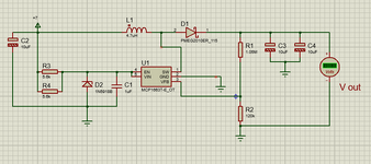
My practical Circuit,
1681216397307.png


I can't understand what happened? Attached the datasheet link below MCP1663 https://ww1.microchip.com/downloads/en/DeviceDoc/20005406A.pdf
 

Attachments

  • MCP1663.jpg
    MCP1663.jpg
    52.9 KB · Views: 130
  • 1681215957204.png
    1681215957204.png
    19.5 KB · Views: 123

You might start by figuring the inductor's maximum
"charge" (volt-seconds when "on") and what that "slug"
should deliver for current to the load, as total charge.
Then you can multiply that by chop frequency and see
how much current can be delivered.

Your on time is the charge and the chop rate makes that
the current.

You might have too short a dwell time. You might have
too small an inductor and be saturating it, wasting much
current and stressing power devices. You might have too
slow a chop rate. And of course the charge and the
discharge should both fit into a cycle (DCM) if that is
the control style, though CCM will throw more current.

Be aware that boost converters really suffer for efficiency
at high boost ratios, and a flyback might be a better
choice if you expect always a similar boost ratio. The
transformer ratio can also put you more toward a 50%
center duty cycle vs line / load / make / temp. I'd bet that
you can find plenty of well modeled, suitable core capacity
flyback xfmrs at distributors, and guidance on selection
at major vendors.
 

Hi,

I guess: too high load current

Klaus
Hi,
I am just connect 1 led only. It's not High load.
--- Updated ---

the tiny 9V battery you are using for the power source cannot supply the current needed for your load
--- Updated ---

I also tried with DC power supply source. But Same issue is replicated here.
 

Did you run the boost converter with no load attached? Even for as brief as half a second? There's a chance it caused output voltage to soar to damaging levels.

The data sheet states 500kHz switching frequency. This bare-bones simulation gives an idea what waveforms to expect in your system. The 1/2 ohm resistor represents some amount of parasitic resistance.

Notice average inductor current is merely 389 mA (for 4.7uH). Yet the peak reaches 1 Ampere, which requires saturation rating of 1 Ampere. This is due to operating in discontinuous mode. If instead you were to choose 10 or 15 uH inductor, you could operate in continuous current mode allowing you to get by with a lesser saturation rating, maybe 600mA.

boost converter 7V supply clk-driven 500kHz to 12V 200mA.png
 

It is possible you built it wrong - always pays to check - also the chip could be dead from previous efforts to use it ... (?)
 

My bench boards, I always make anything with more than 3 leads socketed.

Super high speed stuff may need more care with socket and package
selection (or bumped die product, fuggedaboudit) but enabling A/B
testing on your "WTF?"s sure helps with debug.
 

Hi,

while dick_freebird's way is valid ... I do it just the opposite way: no sockets, even no simulation before.
I guess there is no right or wrong. You have to find your own way.

***
Load current guessing: I miss a lot of other informations, like:
* exact part numbers & manufacturer name (critical parts: coil, capacitors...)
* PCB layout (especially DCDC converters are PCB layout critical. Usuallly there is a layout recommendation in the datasheet)
* test conditions
* scope pictures
* DVM readings

Klaus
 

Status
Not open for further replies.

Similar threads

Part and Inventory Search

Welcome to EDABoard.com

Sponsor

Back
Top