Continue to Site

Welcome to EDAboard.com

Welcome to our site! EDAboard.com is an international Electronics Discussion Forum focused on EDA software, circuits, schematics, books, theory, papers, asic, pld, 8051, DSP, Network, RF, Analog Design, PCB, Service Manuals... and a whole lot more! To participate you need to register. Registration is free. Click here to register now.

[SOLVED] 2 Amp 16 Volt Power supply problem

Status
Not open for further replies.
200 pcs of IN4007 are available in our local market for 1$.
 

that is nice, but our point of interest is at 3 amps diodes and making a bridge vs a ready made bridge.
 

Actually you don't have to bother about cost for prototyping or assembling one unit for your hobby. I like ready made bridge only because they look smart and occupy less space. Although cost more but easy to tie with a heat sink. On the other hand, there are some rectifiers which are cheap and operate very good. During a test for over current, the solder joint melted due to heat but diode survived. I think there is difference in product performances although printed with same part number. Its due to competition in general purpose parts used widely in locally manufactured products.
It is good practice to use high current rating diodes in such application as it is usual that 2Amp supply can deliver current at more than 6Amps during short circuits.
 

Repalce your 1N4007 with 1N5408 or use a monolithic bridge rectifier package. Bacause, the 1N400X series an hold only 1A
 

IN4001 and IN5401 are for low voltage use. they have low forward drop with respect to high voltage parts and hence perform better.
 

Some people have to literally watch their pennies. For many, a difference of $1 is not a trivial matter.
 

That was in response to your statement about not having to bother about cost for prototyping or assembling one unit for a hobby.
 

I am myself in this habit of replacing parts that cost less. I am easily carried away with a price offer of a very small difference. I even delay my project, if i know i'll get that part for less. It is more like an obsession, i am now trying to overcome, That's why i say,
you don't have to bother about cost for prototyping or assembling one unit for your hobby
 

which fuse rating should i use before the transformer and also after the transformer and why??
 

Fuse will protect against fire hazard, blown recifiers and transformer due to overload and short circuit.
Use ohm law to find current consumption with maximum expected output. Put a fuse with slightly a higher value to that.
 

Well ... guys ... i am quit surprised that the problem of thread poster has solved and even then a quit long discussion have been made just on a basic power supply bridge rectifier circuit ... lolzzzzzzzzz.....
But the most surprising part it that i have yet learnt lot of new things from this discussion i as being experiencing electronics from quit few years i never suposed this topic too much discussed able , even i have not made the bridge on my own hand from some years , but realy guys i have learnt some new things too i did not finishd whole thread but i hope it will also be usefull i will do this on some other time(may b)
thnks guys :)
 

I am myself in this habit of replacing parts that cost less. I am easily carried away with a price offer of a very small difference. I even delay my project, if i know i'll get that part for less. It is more like an obsession, i am now trying to overcome, That's why i say,
you don't have to bother about cost for prototyping or assembling one unit for your hobby
There's nothing wrong with using the cheapest parts that do the job. But it's also a waste of your time if it's for prototyping / one-offs only, and the cost difference is something you would earn (in a regular job) in much less time than you'd spend on using the lower-cost parts vs. more convenient ones.

So there is an optimum that depends on component prices, your 'disposable income', and how much you consider your time is worth. If you want to use something solely for the learning aspect: go ahead. But other than that: "premature optimization is the root of all evil". :evil: :lol:

Personally I simply keep a design's ultimate purpose / long-time use in mind, and choose according to that. For experiments, whatever I've got lying around will do. For something that I'll use myself for years to come, I try to make it the best I can within my budget (but no reason to go overboard, mostly I end up picking best performance/price ratio). For something I might build in series: optimize for low cost, efficiency, easy construction & reliability. Often there's some conflict between those factors... :cry:
 
Last edited:
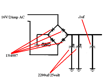
i have a 16v 2 amp transformer, i make a bridge with 1N4007 and after the bridge two 2200uf/25volt and a .1uf disc type capacitor is paralleled. now when i switched on, two of my diodes is burned... can anyone help me to rectify this problem. i am a newbie to electronics. thanks in advance. here is my schematic:


you have to replace the diode bridge, if you want the current 2 amps, you should use a diode bridge 2 amps.
 

There's nothing wrong with your circuit. Maybe you made a mistake in your actual wiring. Double-check the polarities of the diodes and the two 2200/25 capacitors.

you said that check the polarities of the capacitor .
i have a question if capacitor at the input side with reverse polarity is connected would that effect the diode at the inner side?
 

Status
Not open for further replies.

Part and Inventory Search

Welcome to EDABoard.com

Sponsor

Back
Top