Continue to Site

Welcome to EDAboard.com

Welcome to our site! EDAboard.com is an international Electronics Discussion Forum focused on EDA software, circuits, schematics, books, theory, papers, asic, pld, 8051, DSP, Network, RF, Analog Design, PCB, Service Manuals... and a whole lot more! To participate you need to register. Registration is free. Click here to register now.

Rs485 signal level clarifications

Status
Not open for further replies.

garimella

Full Member level 5
Joined
Aug 25, 2011
Messages
260
Helped
0
Reputation
0
Reaction score
0
Trophy points
1,296
Activity points
3,276
I was referring to MAX485 datasheet which specifies that it can accept input range from -7V to +12V. I am not clear how the device can accept this wide range as it is powered only with 5V. How does it deal with negative voltages? And also not sure what voltages would appear at MAX485 differential outputs ( I guess +/-2.5V or may be +5V/0V)
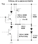
 

They use resistive voltage dividers and isolation diodes. Unfortunately Maxim doesn't manage to show an instructive schematic, refer to competitors datasheets to see how it's achieved.

See the port structure of TI sn75lbc176

sn75lbc176.PNG
 

Hi

The diagram suggests that output is unipolar for both ports A and B (more like totem pole arrangement). No bipolar outputs are produced.
 

Sure, A and B signals are unipolar, differential signal A-B is bipolar.


MAX485 outputs A and B are e.g. swinging between 1.5 and 3.5 V with 50 ohm differential load (100 ohm termination at both bus ends), generating +/- 2V differential signal.
 

Status
Not open for further replies.

Part and Inventory Search

Welcome to EDABoard.com

Sponsor

Back
Top