Continue to Site

Welcome to EDAboard.com

Welcome to our site! EDAboard.com is an international Electronics Discussion Forum focused on EDA software, circuits, schematics, books, theory, papers, asic, pld, 8051, DSP, Network, RF, Analog Design, PCB, Service Manuals... and a whole lot more! To participate you need to register. Registration is free. Click here to register now.

Some problem with simulation by SONNET IE3D and HFSS

Status
Not open for further replies.

xd2186

Newbie level 6
Joined
Apr 27, 2018
Messages
12
Helped
0
Reputation
0
Reaction score
0
Trophy points
1
Activity points
77
Hi every guys.
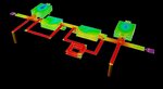
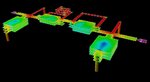
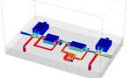
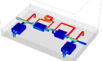
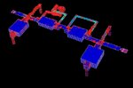
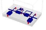
I am performing a simulation optimization for a LTCC filter,But very different result between IE3D and HFSS&SONNET, SONNET and HFSSresults were almost identical.Pictures are as follows. IE3D_f.jpgIE3D_R.jpgsonnet_f.jpgsonnet_r.jpgHFSS_f.jpgHFSS_r.jpg

Why does this happen? who can help me? Thanks in advance.:-x
 

All model was created by DXF output of IE3D, maybe some wrong with HFSS&SONNET setting?
 

All model was created by DXF output of IE3D, maybe some wrong with HFSS&SONNET setting?

DXF gives you the polygons in the x-y plane, but there can be mistakes in the stackup, or in the modelling of conductor thickness, or boundary condition, or mesh. Sonnet and HFSS results are also very different if you look at the upper stopband. Can you upload the Sonnet model?
 

DXF gives you the polygons in the x-y plane, but there can be mistakes in the stackup, or in the modelling of conductor thickness, or boundary condition, or mesh. Sonnet and HFSS results are also very different if you look at the upper stopband. Can you upload the Sonnet model?

That is Sonnet model and HFSS model.thanks
 

Attachments

  • sonnet&hfss file.zip
    176.3 KB · Views: 48

The Result of IE3D is "too good"..Others seem more realistic..
 
  • Like
Reactions: xd2186

    xd2186

    Points: 2
    Helpful Answer Positive Rating
In Sonnet you have defined 3µm conductor thickness for loss, but used thin sheet (zero thickness) for the actual EM model meshing.
You have defined 45µm dielectric, is that between the metal conductors? Or do the 3µm metals penetrate into the dielectric, for an effective 45µm - 3µm = 42mm distance in the capacitors?
 

Your Sonnet model is essentially OK. You should use thick metal modelling and a smaller cell size, that has some effect.
I have used Sonnet a lot for LTCC work and trust results - if the layout and stackup are accurate.

s21.PNG
S11.PNG

Updated models:
View attachment bpf2070_5_volker.zip
 
  • Like
Reactions: xd2186

    xd2186

    Points: 2
    Helpful Answer Positive Rating
The Result of IE3D is "too good"..Others seem more realistic..

I used IE3D for some microwave planar circuits such as microstrip filters, it is very accuracy. Why is IE3D inefficient for 3D circuits(LTCC)?
 

In Sonnet you have defined 3µm conductor thickness for loss, but used thin sheet (zero thickness) for the actual EM model meshing.
You have defined 45µm dielectric, is that between the metal conductors? Or do the 3µm metals penetrate into the dielectric, for an effective 45µm - 3µm = 42mm distance in the capacitors?

I have considerd it.The ceramic layer thickness is 42.5um(greentape is dupont 951 50um),conductor is 3um.In my experience,just defined 45um.


I have compared results of IE3D and sonnet, This is example of IE3D, I have exported dxf by IE3D and created model in sonnet.
There are some different between them yet.

LTCC_BPF_i_m.jpgLTCC_BPF_i.jpgLTCC_BPF_s_m.jpgLTCC_BPF_s.jpg
 

Attachments

  • LTCC_BPF.zip
    1.9 KB · Views: 38

I don't know how good and accurate that IE3D model is. Here is an LTCC appnote that my colleague created long ago with Sonnet. That includes measured vs. simulated.

View attachment MWEE_JuneJuly03.pdf

However, in your last Sonnet model you have some poor connections (round via in square cutout).

badconnection.PNG

Also, don't forget that Sonnet analyzes in a metal box (=ground). You might want to keep some more distance to the side walls. Some of your lines are rather close and parallel to the box side walls.
 
Last edited:

It is my fault.I'm so careless.For your suggestion, I modified the sonnet model.Result difference between sonnet and IE3D is small now.
LTCC_BPF_s1.jpg

I will continue to find mistakes in IE3D model.

Thanks you very much!
 

Attachments

  • LTCC_BPF.zip
    1.8 KB · Views: 38

One area that you can check: the mesh in overlapping metal polygons. Only if the mesh is fine enough or aligned, the correct charges can be placed on the mesh and capacitance is accurate.

Sonnet does that mesh alignment on adjacent layers automatically. For IE3D, you can visually check the mesh: it should have mesh boundaries where the capacitor metals overlap. This allows to place charge in the large metal plates with the exact size of the overlapping smaller polygon.
 
  • Like
Reactions: xd2186

    xd2186

    Points: 2
    Helpful Answer Positive Rating
One area that you can check: the mesh in overlapping metal polygons. Only if the mesh is fine enough or aligned, the correct charges can be placed on the mesh and capacitance is accurate.

Sonnet does that mesh alignment on adjacent layers automatically. For IE3D, you can visually check the mesh: it should have mesh boundaries where the capacitor metals overlap. This allows to place charge in the large metal plates with the exact size of the overlapping smaller polygon.


The problem hasn't been solved, thank you all the same! :):)
 

One area that you can check: the mesh in overlapping metal polygons. Only if the mesh is fine enough or aligned, the correct charges can be placed on the mesh and capacitance is accurate.

Sonnet does that mesh alignment on adjacent layers automatically. For IE3D, you can visually check the mesh: it should have mesh boundaries where the capacitor metals overlap. This allows to place charge in the large metal plates with the exact size of the overlapping smaller polygon.

I have compared difference of current distribution between IE3D and sonnet, but it look like simular. I have no idear:bang:

Current display parameter:mad:2GHz 0deg.
 

Attachments

  • current_i_1.jpg
    current_i_1.jpg
    99.7 KB · Views: 58
  • current_i_2.jpg
    current_i_2.jpg
    90.9 KB · Views: 51
  • current_s_1.jpg
    current_s_1.jpg
    238.8 KB · Views: 50
  • current_s_2.jpg
    current_s_2.jpg
    237.7 KB · Views: 57

For the capacitors, we want to see charge (not currents). Sonnet can plot charge, for IE3D I don't know.

The problem that I mentioned is seen when capacitor plates have different size. For this case with equal sizes, there should be no mesh alignment issue anyway.

The IE3D currents look a bit coarse to me.

I can't find charge display module in IE3D, be insteaded by vector current.I have plot charge response by sonnet,I don't know if it is correct.
 

Attachments

  • current_i_3.jpg
    current_i_3.jpg
    97.8 KB · Views: 55
  • current_s_3.jpg
    current_s_3.jpg
    161.8 KB · Views: 51

For the capacitors, we want to see charge (not currents). Sonnet can plot charge, for IE3D I don't know.

The problem that I mentioned is seen when capacitor plates have different size. For this case with equal sizes, there should be no mesh alignment issue anyway.

The IE3D currents look a bit coarse to me.

SONNET optimization ability is unsatisfactory ,only one mothed to optimize.How can I improve it .
It seem like AWR and IE3D ability to optimize obvious much better than sonnet.
 

Status
Not open for further replies.

Part and Inventory Search

Welcome to EDABoard.com

Sponsor

Back
Top