Continue to Site

Welcome to EDAboard.com

Welcome to our site! EDAboard.com is an international Electronics Discussion Forum focused on EDA software, circuits, schematics, books, theory, papers, asic, pld, 8051, DSP, Network, RF, Analog Design, PCB, Service Manuals... and a whole lot more! To participate you need to register. Registration is free. Click here to register now.

PIC16F1937 for PWM generation for H-Bridge control

Status
Not open for further replies.

jean12

Advanced Member level 2
Joined
Aug 27, 2013
Messages
529
Helped
5
Reputation
12
Reaction score
6
Trophy points
18
Activity points
5,497

If you want sine modulated H-bridge circuit. Go for Half bridge connected as full bridge connections as shown in figure 23-9 in PIC16F1937 datasheet.

For settings 10KHz PWM at 4MHz oscillator, set Timer2 and EPWM1 as follows
Code:
unsigned char sr_10k_signal_500[] = {0, 31, 58, 80, 94, 99, 94, 80, 58, 31, 0, -31, -58, -80, -94, -99, -94, -80, -58, -31};

// Port settings
TRISC2 = 0; // P1A
TRISD5 = 0; // P1B
TRISD6 = 0; // P1C;
TRISD7 = 0; // P1D;

// ECCP settings
CCP1CON = 0b10001111; // Enable EPWM in Half bridge mode, active low PWMs
CCPTMRS0 = 0b11111100; // Timer2 is timebase for PWM1
CCP1AS = 0b00011010; // Comparator 1 autoshutdown is enabled with output goes to tri-state after shutdown
PWM1CON = 0b10000100; // PWM1 auto shutdown restart is enabled with 4 times instruction clock dead band
PSTR1CON = 0b00010000; // Uninverted PWM outputs will appear on port pins
CCPR1 = 49 //Initial 50% duty cycle to start from 0

// Timer 2 settings
T2CON = 0b00000100;
T2PR = 99; // ((Fosc/4)/10k)-1 is the period count

I used 500Hz frequency as an example since it has lesser sample count at 10kHz sampling rate. If application is an inverter 50Hz at 10kHz sampling will have 200 samples. Use excel sheet to generate sine samples. 1st column be sample number or integer time interval, 2nd column be sine formula like =SIN(2*PI()*(signalFreq/10000)*n) n is sample numbers, 3rd column be =ROUND(sin_sample*99, 0).

U will get your samples.

Hope that helps.


I do not understand: you are using half bridge or full bridge? For debugging the software, you may start with a smaller number and then increase the final resolution.
 

I am using the full bridge (4IGBTs) but all four signals has to be at 10KHZ.

Please help
 

I am using the full bridge (4IGBTs) but all four signals has to be at 10KHZ.

10kHz base modulated with 50Hz sine wave in PWM, 256 points per cycle (or half/ quarter cycle)? Are you putting dead time in software or in hardware? Are you using hardware complementary outputs or they too are coming from the PIC?
 

Hello,here are my codes
Code:
  unsigned char sin_table[32]={0, 10, 19, 29, 38, 47,
   55, 63, 70, 77, 82, 87, 91, 95, 97, 
  99, 99, 99, 97, 95, 91, 87, 82, 77, 70, 63, 55, 47, 38, 29, 19, 10};

unsigned int TBL_POINTER_NEW, TBL_POINTER_OLD, TBL_POINTER_SHIFT, SET_FREQ;
unsigned int TBL_temp;
unsigned char DUTY_CYCLE;


//Set LCD Bits for DATA Direction

sbit LCD_RS at RD0_bit;
sbit LCD_EN at RC3_bit;
sbit LCD_D4 at RC4_bit;
sbit LCD_D5 at RC5_bit;
sbit LCD_D6 at RC6_bit;
sbit LCD_D7 at RC7_bit;

sbit LCD_RS_Direction at TRISD0_bit;
sbit LCD_EN_Direction at TRISC3_bit;
sbit LCD_D4_Direction at TRISC4_bit;
sbit LCD_D5_Direction at TRISC5_bit;
sbit LCD_D6_Direction at TRISC6_bit;
sbit LCD_D7_Direction at TRISC7_bit;

void interrupt(){
     if (TMR2IF_bit == 1){
        TBL_POINTER_NEW = TBL_POINTER_OLD + SET_FREQ;
        if (TBL_POINTER_NEW < TBL_POINTER_OLD){
           CCP1CON.P1M1 = ~CCP1CON.P1M1; //Reverse direction of full-bridge
        }
        //TBL_POINTER_SHIFT = TBL_POINTER_NEW >> 11;
        TBL_POINTER_SHIFT = TBL_POINTER_NEW >> 13;//10KHZ
        DUTY_CYCLE = TBL_POINTER_SHIFT;
        CCPR1L = sin_table[DUTY_CYCLE];
        TBL_POINTER_OLD = TBL_POINTER_NEW;
        TMR2IF_bit = 0;
     }}
void main() {
     Lcd_Init();
    LCD_Cmd(_LCD_CLEAR);
    LCD_Cmd(_LCD_CURSOR_OFF);


    SET_FREQ=512;//50HZ at 12MHZ with 20MHZ and 32 values
     TBL_POINTER_SHIFT = 0;
     TBL_POINTER_NEW = 0;
     TBL_POINTER_OLD = 0;
     DUTY_CYCLE = 0;
     ANSELA = 0x0F; //Enable Analog Reading for RA0-RA3
     PR2=99;
     TRISC = 0x07;    //Only RC2 is output
     PORTC=0X07;
     TRISD=0;
     PORTD=0;
     TRISA=0x0F;
     PORTA=0x0F;
     TRISB=0X01;
     PORTB=0x01;
     CCP1CON = 0b00001101;
    PWM1CON=0X80;
     TMR2IF_bit = 0;
     T2CON =0X04; //TMR2 on, prescaler and postscaler 1:1
     while (TMR2IF_bit == 0);
     TMR2IF_bit = 0;
     TRISC = 0x00;
     TRISD=0X00;
     TMR2IE_bit = 1;
     GIE_bit = 1;
     PEIE_bit = 1;
     //ADC Initialization

       // ADC_Init();
     while(1)
     {

    }
}
,I want both the 4 signals to come from P1A,P1B,P1C and P1D of my PIC16F1937 all at 10KHZ,refer to my code above for the sine wave[look up table],I am using 32 values at 180 degrees

Best Regards
 

I have went through all those pages you are telling me but the way found there is to generate a carrier signal of 16KHZ(for low sideMOSFET) for example and a signal of 50HZ on two pin(for high side MOSFET).

Me I want to use on both side that high frequency different to 50Hz to use for example 10KHZ for both side as I the signal do have to pass through other components before attaining the MOSFET gate.

This is a system I am repairing(DC-AC Converter) which used 10KHZ for both side but with dsPIC3010F6010,so I want to generate the same signal but using PIC16F1937 (4 signals of 10KHZ where 2 are used for high side and 2 others for low side).

Please help
 
I want to use on both side that high frequency

You should use half bridge configuration for ECCP module

One Pin of Micro controller attach with opposite legs of H bridge (Two MOSFETS)
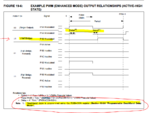
Image attached from datasheet of PIC 16F1937
Page # 184
Capture.PNG

Page 192
Capture1.PNG
Page 196
Capture3.PNG

Page 207
Capture4.PNG

Frequency and duty cycle can be calculated from given references and write program according to fist reply Thread #8


______Always Appreciate for good Replies_______
 
Thank you for the reply,
I understand all those basics,but referring to thread #8,with Tahmid how may I calculate the
SET_FREQ=?
Shifting numbers,etc so that I get the 10KHZ on all pins of the PIC16F1937?For physical connections I understand very well!!

Please help
 

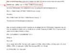
Lets say your frequency is 10kHz

PWM period = 1/10000

then calculate PR2 value
Capture.PNG


Hit Helped me If you find an answer helful
 
The problem is not PR2 value but the sine table my friend!!
 

Why do you want to use sine table?
just update CCPR1L register with a single value
 
could you show me so that I can understand more?
Thanks
 

Status
Not open for further replies.

Similar threads

Part and Inventory Search

Welcome to EDABoard.com

Sponsor

Back
Top